Voltage Limiting Devices

Voltage Limiting Device

  • Electrical isolation of insulated track sections and earthed parts of installations
  • Safe equipotential bonding in case of a short-circuit or earth fault at the overhead contact line due to high-current-resistant welding of the electrodes
  • Discharge of lightning surges without short-circuit formation due to lightning-resistant SDS ... voltage limiting device
  • Short-circuit withstand capability up to 25 kArms / 100 ms; 36 kArms / 75 ms

Version

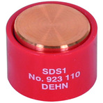
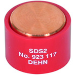
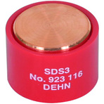
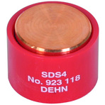
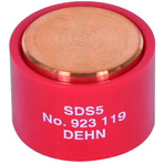
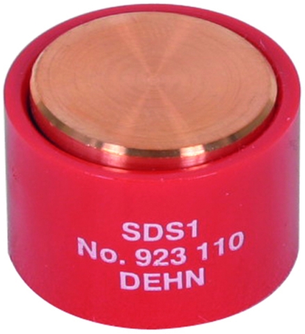
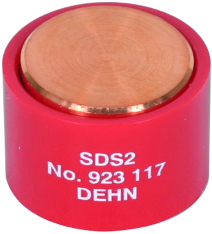
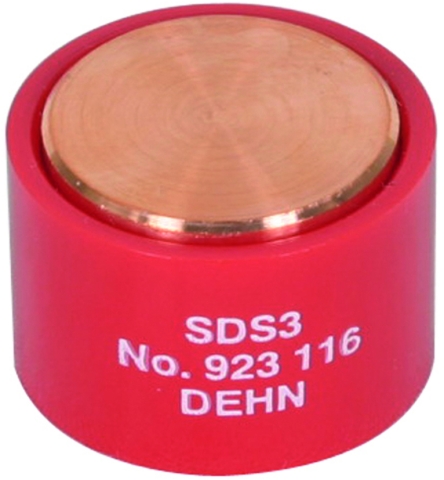
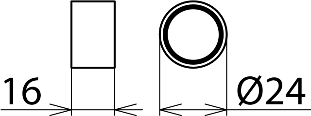
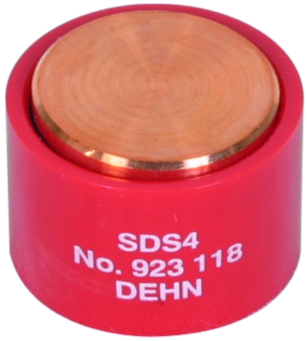
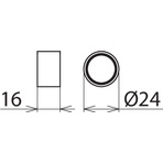
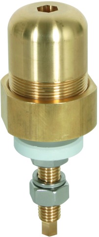
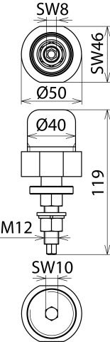
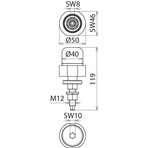
SDS ...: Cylindrical SDS spark gap unit for use with MA SDS M12 mast adapter

Details

EN 50122-1 describes the use of voltage limiting devices for d.c. and a.c. traction systems for so-called "open traction system earthing" of conductive components of the overhead contact line and pantograph zone.
Voltage limiting devices (SDS ...) are used to prevent the occurrence of hazardous surges between the insulated tracks or track sections of electric railways and earthed parts of the installation.

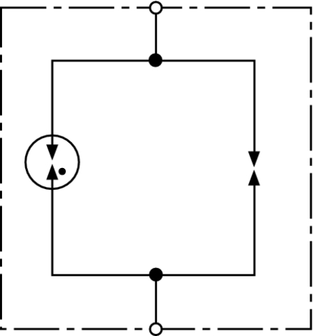
Their function is to permanently connect parts of the installation in the overhead contact line and pantograph zone to the return circuit as soon as the threshold voltage is exceeded.

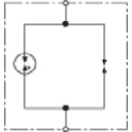
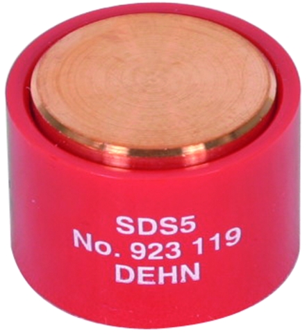
In case of atmospheric overvoltages, the lightning-resistant SDS ... voltage limiting device is capable of returning to its initial state after discharging the impulse current. Only if the specified lightning current load is exceeded, a permanent short-circuit is initiated by high-current-resistant welding of the electrodes and the fuse link has to be replaced.

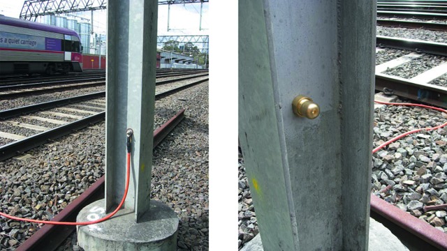
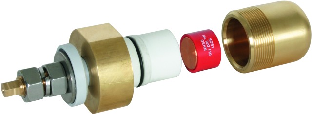
The SDS voltage limiting device consists of a spark gap unit and the respective connecting kit and can be directly connected to the rail or overhead contact line tower.

The spark gap unit of type SDS 1 (Part No. 923 110) developed by DEHN has also been approved by the German Federal Railway Authority (EBA).

Models

SDS 1

SDS 2

SDS 3

SDS 4

SDS 5

SDS 1

Basic circuit diagram SDS 1Dimension drawing SDS 1

Voltage limiting device for a power-frequency sparkover voltage ≤ 940 V.


Specifications

Type
Part No.
VLD type (EN 50122-1)
Power frequency sparkover voltage (Uaw)
d.c. sparkover voltage (Uag)
Impulse sparkover voltage
Self-extinguishing capability
Lightning current discharge capacity (10/350 µs) 0.1x / 0.5x / 1x
Lightning current withstand capability (10/350 µs)
Safe short-circuit due to welding of the electrodes in case of alternating currents
Safe short-circuit due to welding of the electrodes in case of direct currents
Short-circuit withstand capability
Long-term current
Leakage current (Ilc)
Operating temperature range (TU)
To be mounted with
Approvals
DB drawing No.
Weight
GTIN
PU
Part No.
  • SDS 1
  • 923 110
  • VLD-F
  • ≤ 940 V
  • 600 V +/- 20 %
  • ≤ 1400 V (1kV/µs)
  • 300 A / 65 V
  • 5 kA
  • 25 kA
  • ≥ 2.5 kA / 1000 V / 30 ms, ≥ 1.5 kA / 1000 V / 100 ms
  • ≥ 750 A / 250 ms
  • 25 kArms / 100 ms; 36 kArms / 75 ms
  • 1 kArms for t ≤ 120 s
  • < 1 µA for 100 V d.c.
  • -40 °C ... +80 °C
  • mast adapter MA SDS M12 or SIEMENS No. 8WL6503-xx
  • EBA
  • 4 Ebs 15.13.20 Sheet 2
  • 40 g
  • 4013364092426
  • 10 pc(s)
  • 923 110
  • Specifications (PDF)
  • More

SDS 2

Basic circuit diagram SDS 2Dimension drawing SDS 2

Voltage limiting device for a d.c. sparkover voltage of 350 V.


Specifications

Type
Part No.
VLD type (EN 50122-1)
d.c. sparkover voltage (Uag)
Impulse sparkover voltage
Lightning current discharge capacity (10/350 µs) 0.1x / 0.5x / 1x
Lightning current withstand capability (10/350 µs)
Safe short-circuit due to welding of the electrodes in case of direct currents
Short-circuit withstand capability
Long-term current
Leakage current (Ilc)
Operating temperature range (TU)
To be mounted with
Weight
GTIN
PU
Part No.

SDS 3

Basic circuit diagram SDS 3Dimension drawing SDS 3

Voltage limiting device for a d.c. sparkover voltage of 550 V.


Specifications

Type
Part No.
VLD type (EN 50122-1)
d.c. sparkover voltage (Uag)
Impulse sparkover voltage
Lightning current discharge capacity (10/350 µs) 0.1x / 0.5x / 1x
Lightning current withstand capability (10/350 µs)
Short-circuit withstand capability
Operating temperature range (TU)
To be mounted with
Weight
GTIN
PU

SDS 4

Basic circuit diagram SDS 4Dimension drawing SDS 4

Voltage limiting device for a d.c. sparkover voltage of 230 V.


Specifications

Type
Part No.
VLD type (EN 50122-1)
d.c. sparkover voltage (Uag)
Impulse sparkover voltage
Lightning current discharge capacity (10/350 µs) 0.1x / 0.5x / 1x
Lightning current withstand capability (10/350 µs)
Impulse current discharge capacity (8/20 µs) 0.1x / 0.5x / 1x
Safe short-circuit due to welding of the electrodes in case of direct currents
Short-circuit withstand capability
Long-term current
Leakage current (Ilc)
Operating temperature range (TU)
To be mounted with
Weight
GTIN
PU
Part No.

SDS 5

Basic circuit diagram SDS 5Dimension drawing SDS 5

Voltage limiting device for a d.c. sparkover voltage of 120 V.


Specifications

Type
Part No.
VLD type (EN 50122-1)
d.c. sparkover voltage (Uag)
Impulse sparkover voltage
Lightning current discharge capacity (10/350 µs) 0.1x / 0.5x / 1x
Lightning current withstand capability (10/350 µs)
Impulse current discharge capacity (8/20 µs) 0.1x / 0.5x / 1x
Safe short-circuit due to welding of the electrodes in case of direct currents
Short-circuit withstand capability
Long-term current
Leakage current (Ilc)
Operating temperature range (TU)
To be mounted with
Weight
GTIN
PU
Part No.

Accessories

Mast Adapter for SDS Voltage Limiting Devices

For installation on the mast profile of overhead contact line masts with Ø8-12 mm.

Show SpecificationsHide Specifications

Specifications

Type
Part No.
Lightning current carrying capability (10/350 µs)
Short-circuit withstand capability
Long-term current
Leakage current (Ilc)
Dimensions of the threaded pin
Material
Degree of protection of the inner enclosure
Weight
GTIN
PU