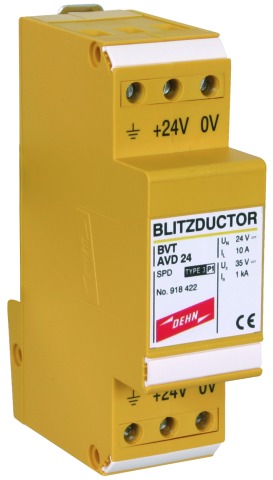
BLITZDUCTOR® VT

Lightning Current / Surge Arrester

Compact DIN rail mounted surge protective device with screw terminals for multi-core lines.
  • Cost-effective protection of multi-core signal lines
  • Interface-specific versions, e.g. RS485 or telecommunication systems
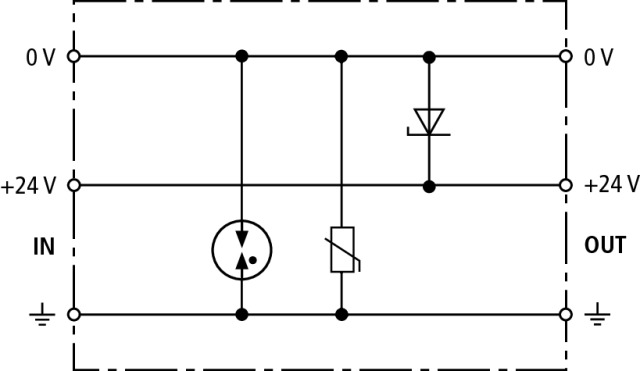
  • Versions for d.c. power supply systems

Description

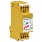
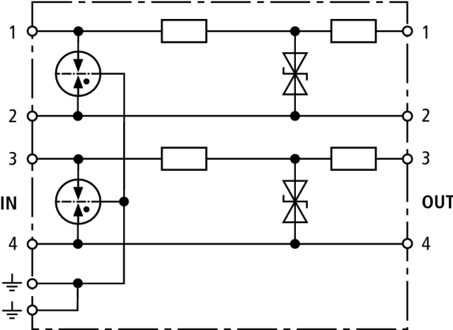
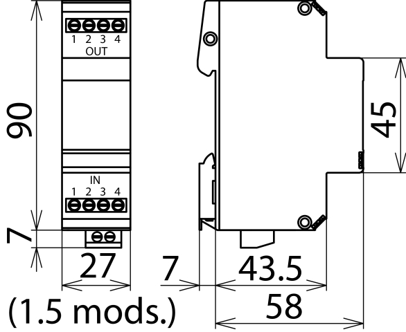
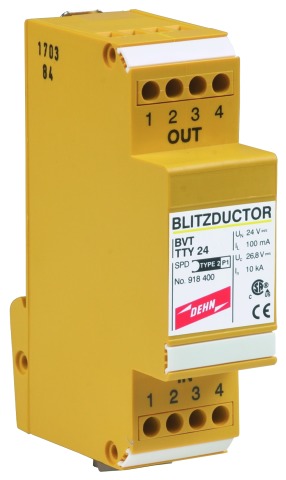
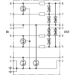
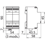
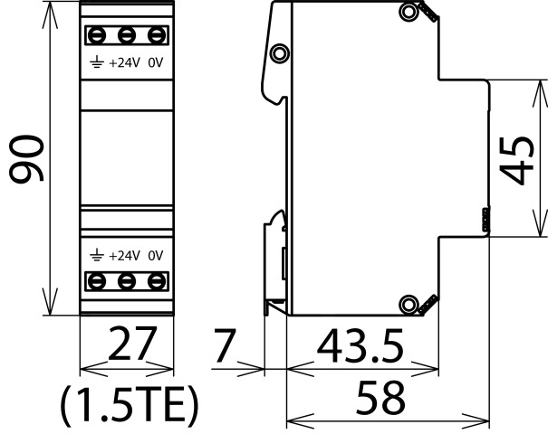
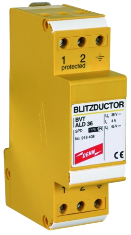
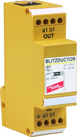
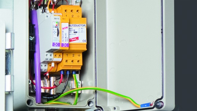
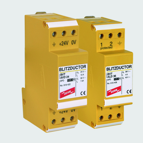
BLITZDUCTOR VT is a family of compact DIN rail mounted arresters and consists of different types of enclosures with different connection methods. Both devices for protecting four-wire signal interfaces with screw connections, but also devices for protecting terminal equipment of telecommunication systems as well as telephone systems with RJ connection are for example available. All types can be mounted on DIN rails and are earthed via a screw terminal.

Different types of BLITZDUCTOR VT arresters are available depending on the application.

Detail 1

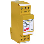
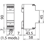
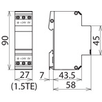
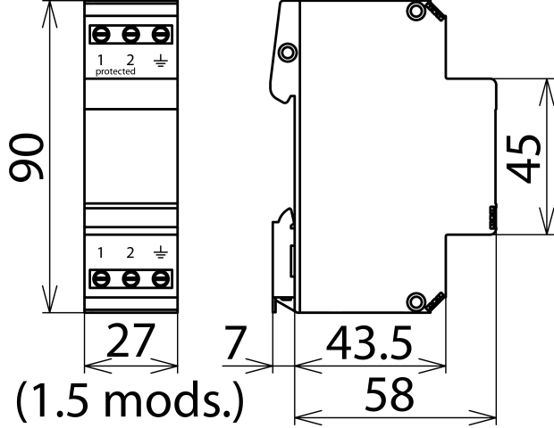
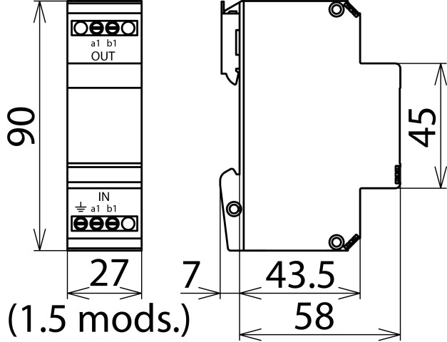
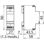
BVT enclosure type with a width of 1.5 modules and screw terminals:
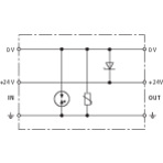
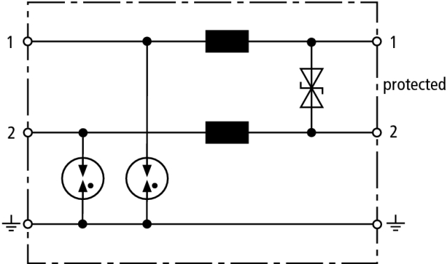
BVT AV/LD: Two protected lines for d.c. power supply systems

Detail 2

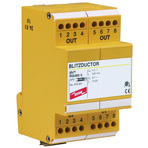
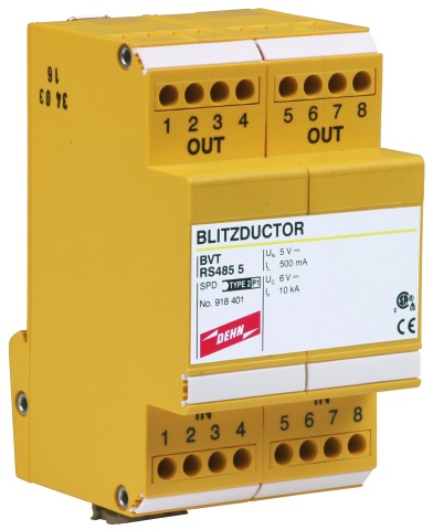
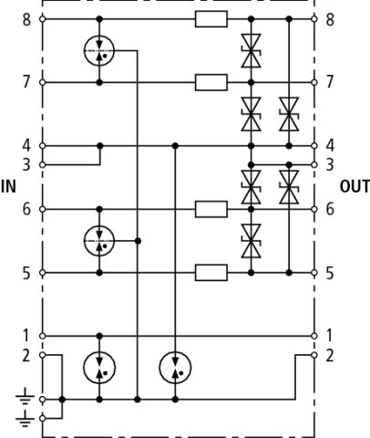
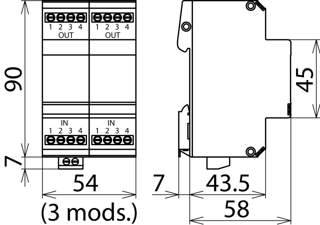
BVT enclosure type with a width of 3 modules and screw terminals:
BVT RS485 specifically designed for protecting RS485 / RS422 interfaces.

Detail 3

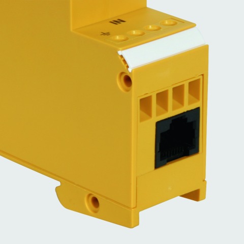
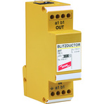
BVT enclosure type with a width of 1.5 modules and RJ connection:
BVT TC1 for protecting telecommunication interfaces.

Detail 4

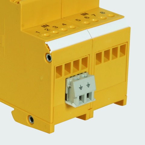
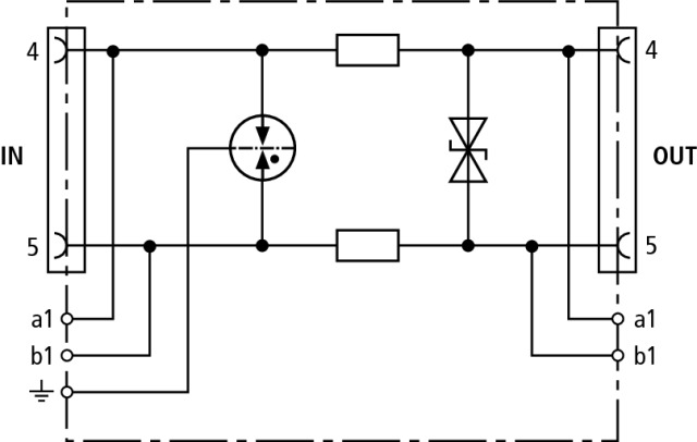
Separate earth connection on the unprotected side of the device. The second slot of the double terminal is intended for connecting the terminal equipment to the equipotential bonding.

Models

BVT TTY

BVT RS485

BVT AVD

BVT ALD

BVT TC

BVT TTY

Basic circuit diagram BVT TTYDimension drawing BVT TTY

Owing to the additional decoupling resistors at the output, even diodes with a low absorption capacity integrated in terminal equipment are energy-coordinated with the protection stages. This is especially important for optocoupler interfaces.


Specifications

Type
Part No.
SPD class
Nominal voltage (d.c.) (UN)
Max. continuous operating voltage (d.c.) (UC)
Nominal current (IL)
D1 Lightning impulse current (10/350 µs) per line (Iimp)
C2 Nominal discharge current (8/20 µs) per line (In)
C2 Total nominal discharge current (8/20 µs) (In)
Voltage protection line-line for In C2 (Up)
Voltage protection level line-PG for In C2 (Up)
Voltage protection level line-line at 1 kV/µs C3 (Up)
Voltage protection level line-PG at 1 kV/µs C3 (UP)
Series resistance per line
Cut-off frequency line-line (fG)
Capacitance line-line (C)
Operating temperature range (TU)
Degree of protection
For mounting on
Connection (input / output)
Cross-sectional area, solid
Cross-sectional area, flexible
Tightening torque (terminals)
Earthing via
Enclosure material
Colour
Test standards
Approvals
Weight
GTIN
PU
Part No.
  • BVT TTY 24
  • 918 400
  • Q
  • 24 V
  • 26.8 V
  • 0.1 A
  • 0.8 kA
  • 10 kA
  • 10 kA
  • ≤ 65 V
  • ≤ 700 V
  • ≤ 36 V
  • ≤ 600 V
  • 17.2 ohms per pair
  • 8 MHz
  • ≤ 1 nF
  • -40 °C ... +80 °C
  • IP 20
  • 35 mm DIN rails acc. to EN 60715
  • screw / screw
  • 0.08-2.5 mm2
  • 0.08-2.5 mm2
  • 0.5 Nm
  • screw terminal
  • thermoplastic, UL 94 V-0
  • yellow
  • IEC 61643-21 / EN 61643-21, UL 497B
  • CSA, EAC
  • 104 g
  • 4013364074231
  • 1 pc(s)
  • 918 400
  • Specifications (PDF)
  • More

BVT RS485

Basic circuit diagram BVT RS485Dimension drawing BVT RS485

Surge arrester for a wide range of applications, e.g. for balanced four-wire RS485/422 interfaces or temperature sensors. Direct or indirect shield earthing, connection of a signal ground (SG).


Specifications

Type
Part No.
SPD class
Nominal voltage (d.c.) (UN)
Max. continuous operating voltage (d.c.) (UC)
Nominal current (IL)
D1 Lightning impulse current (10/350 µs) per line (Iimp)
C2 Nominal discharge current (8/20 µs) per line (In)
C2 Total nominal discharge current (8/20 µs) (In)
Voltage protection line-line for In C2 (Up)
Voltage protection level line-PG for In C2 (Up)
Voltage protection level line-line at 1 kV/µs C3 (Up)
Voltage protection level line-PG at 1 kV/µs C3 (UP)
Series resistance per line
Cut-off frequency line-line (fG)
Capacitance line-line (C)
Operating temperature range (TU)
Degree of protection
For mounting on
Connection (input / output)
Cross-sectional area, solid
Cross-sectional area, flexible
Tightening torque (terminals)
Earthing via
Enclosure material
Colour
Test standards
Approvals
Weight
GTIN
PU
Part No.
  • BVT RS485 5
  • 918 401
  • Q
  • 5 V
  • 6 V
  • 0.5 A
  • 0.8 kA
  • 10 kA
  • 10 kA
  • ≤ 20 V
  • ≤ 700 V
  • ≤ 8.5 V
  • ≤ 600 V
  • 1.8 ohms
  • 1.7 MHz
  • ≤ 5 nF
  • -40 °C ... +80 °C
  • IP 20
  • 35 mm DIN rails acc. to EN 60715
  • screw / screw
  • 0.08-2.5 mm2
  • 0.08-2.5 mm2
  • 0.5 Nm
  • screw terminal
  • thermoplastic, UL 94 V-0
  • yellow
  • IEC 61643-21 / EN 61643-21, UL 497B
  • CSA, EAC
  • 182 g
  • 4013364074224
  • 1 pc(s)
  • 918 401
  • Specifications (PDF)
  • More

BVT AVD

Basic circuit diagram BVT AVDMaßbild BVT AVD

Surge arresters with improved voltage protection levels for EMC protection of electronic components with d.c. voltage supply. Ideally suited for Siemens PLCs. Since a unipolar diode is used, the polarity of the operating voltage must be observed.


Specifications

Type
Part No.
SPD class
Nominal voltage (d.c.) (UN)
Max. continuous operating voltage (d.c.) (UC)
Nominal current at 80 °C (IL)
C2 Nominal discharge current (8/20 µs) per line (In)
C2 Total nominal discharge current (8/20 µs) (In)
Voltage protection line-line for In C2 (Up)
Voltage protection level line-PG for In C2 (Up)
Voltage protection level line-line at 1 kV/µs C3 (Up)
Voltage protection level line-PG at 1 kV/µs C3 (UP)
Capacitance line-line (C)
Capacitance line-PG (C)
Operating temperature range (TU)
Degree of protection
For mounting on
Connection (input / output)
Cross-sectional area, solid
Cross-sectional area, flexible
Tightening torque (terminals)
Earthing via
Enclosure material
Colour
Test standards
Approvals
Weight
GTIN
PU
Part No.
  • BVT AVD 24
  • 918 422
  • W
  • 24 V
  • 35 V
  • 10 A
  • 1  kA
  • 2 kA
  • ≤ 70 V
  • ≤ 500 V
  • ≤ 50 V
  • ≤ 450 V
  • ≤ 7 nF
  • ≤ 1.5 nF
  • -40 °C ... +80 °C
  • IP 20
  • 35 mm DIN rail acc. to EN 60715
  • screw / screw
  • 0.5-6.0 mm2
  • 0.5-4.0 mm2
  • 0.8 Nm
  • screw terminal
  • thermoplastic, UL 94 V-0
  • yellow
  • IEC 61643-21 / EN 61643-21
  • EAC
  • 97 g
  • 4013364149267
  • 1 pc(s)
  • 918 422
  • Specifications (PDF)
  • More

BVT ALD

Basic circuit diagram BVT ALDDimension drawing BVT ALD

Energy-coordinated, DIN rail mounted combined lightning current and surge arrester for protecting unearthed d.c. power supply systems.


Specifications

Type
Part No.
SPD class
Nominal voltage (d.c.) (UN)
Max. continuous operating voltage (d.c.) (UC)
Nominal current at 80 °C (IL)
Nominal current at 45 °C (IL)
Backup fuse if
D1 Lightning impulse current (10/350 µs) per line (Iimp)
D1 Total lightning impulse current (10/350 µs) (Iimp)
C2 Nominal discharge current (8/20 µs) per line (In)
C2 Total nominal discharge current (8/20 µs) (In)
Voltage protection line-line for In C2 (Up)
Voltage protection level line-PG for In C2 (Up)
Voltage protection level line-line at 1 kV/µs C3 (Up)
Voltage protection level line-PG at 1 kV/µs C3 (UP)
Series resistance per line
Capacitance line-line (C)
Capacitance line-PG (C)
Operating temperature range (TU)
Degree of protection
For mounting on
Connection (input / output)
Cross-sectional area, solid
Cross-sectional area, flexible
Tightening torque (terminals)
Earthing via
Enclosure material
Colour
Test standards
Approvals
Weight
GTIN
PU
Part No.
  • BVT ALD 36
  • 918 408
  • M
  • 36 V
  • 45 V
  • 4 A
  • 7 A
  •  
  • 2.5 kA
  • 5 kA
  • 10 kA
  • 20 kA
  • ≤ 80 V
  • ≤ 1000 V
  • ≤ 60 V
  • ≤ 650 V
  • 22 µH
  • ≤ 1.5 pF
  • ≤ 100 pF
  • -40 °C ... +80 °C
  • IP 20
  • 35 mm DIN rails acc. to EN 60715
  • screw / screw
  • 0.5-6.0 mm2
  • 0.5-4.0 mm2
  • 0.8 Nm
  • screw terminal
  • thermoplastic, UL 94 V-0
  • yellow
  • IEC 61643-21 / EN 61643-21
  • UL, EAC
  • 110 g
  • 4013364125292
  • 1 pc(s)
  • 918 408
  • Specifications (PDF)
  • More
  • BVT ALD 60
  • 918 409
  • M
  • 60 V
  • 65 V
  • 4 A
  • 7 A
  • UN ≥ 45 V and IL ≥ 1 A
  • 2.5 kA
  • 5 kA
  • 10 kA
  • 20 kA
  • ≤ 120 V
  • ≤ 1000 V
  • ≤ 90 V
  • ≤ 650 V
  • 22 µH
  • ≤ 1.0 nF
  • ≤ 100 pF
  • -40 °C ... +80 °C
  • IP 20
  • 35 mm DIN rails acc. to EN 60715
  • screw / screw
  • 0.5-6.0 mm2
  • 0.5-4.0 mm2
  • 0.8 Nm
  • screw terminal
  • thermoplastic, UL 94 V-0
  • yellow
  • IEC 61643-21 / EN 61643-21
  • UL, EAC
  • 110 g
  • 4013364146709
  • 1 pc(s)
  • 918 409
  • Specifications (PDF)
  • More

BVT TC

Basic circuit diagram BVT TCDimension drawing BVT TC

Energy-coordinated and leakage-current-free surge arrester for a/b lines, ISDN Uk0 or ADSL with RJ45 connections and additional screw terminals. Pinning of the RJ45 sockets is compatible with RJ11/12. The parallel screw terminals are more robust than the RJ45 sockets and increase the total nominal discharge current to 10 kA.


Specifications

Type
Part No.
SPD class
Nominal voltage (UN)
Max. continuous operating voltage (d.c.) (UC)
Nominal current (IL)
D1 Lightning impulse current (10/350 µs) per line (Iimp)
C2 Nominal discharge current (8/20 µs) per line (In)
C2 Total nominal discharge current (8/20 µs) (In)
Voltage protection line-line for In C2 (Up)
Voltage protection level line-PG for In C2 (Up)
Voltage protection level line-line at 1 kV/µs C3 (Up)
Voltage protection level line-PG at 1 kV/µs C3 (UP)
Series resistance per line
Cut-off frequency line-line (fG)
Capacitance line-line (C)
Capacitance line-PG (C)
Operating temperature range (TU)
Degree of protection
For mounting on
Connection (input / output)
Pinning
Cross-sectional area, solid
Cross-sectional area, flexible
Earthing via
Enclosure material
Colour
Test standards
Approvals
Weight
GTIN
PU
Part No.
  • BVT TC 1
  • 918 411
  • R
  • 130 V
  • 170 V
  • 0.2 A
  • 1 kA
  • 2.5 kA
  • 5 kA
  • ≤ 275 V
  • ≤ 600 V
  • ≤ 240 V
  • ≤ 600 V
  • 4.7 ohms
  • 17 MHz
  • ≤ 300 pF
  • ≤ 15 pF
  • -40 °C ... +80 °C
  • IP 10
  • 35 mm DIN rails acc. to EN 60715
  • RJ45 or terminals / RJ45 or terminals
  • 4/5
  • 0.08 - 2.5 mm2
  • 0.08 - 2.5 mm2
  • screw terminal
  • thermoplastic, UL 94 V-0
  • yellow
  • IEC 61643-21 / EN 61643-21
  • EAC
  • 99 g
  • 4013364093133
  • 1 pc(s)
  • 918 411
  • Specifications (PDF)
  • More
    • Further Pictures
      Basic circuit diagram BVT TC
      open PDF
      Dimension drawing  BVT TC
      open PDF
      Further Information
      Product Specifications (Text)

      Back

      Coordinated BVT TC 1 leakage-current-free surge arrester
      Surge arrester BLITZDUCTOR VT, SPD class 
      TYPE 2/P2, tested acc. to EN 61643-21 
      and energy coordinated acc. to IEC 61643-22 
      for the protection of analoge modems in switchgear 
      cabinets, also for ASDL, ISDN Uko, 2 pole, 
      installation width 1,5 TE, connection via 
      RJ45(12)-socket or screw terminals
      
      Max. continuous operating voltage (d.c.): 170 V
      Nominal current: 0.2 A
      C2 Total nominal discharge current (8/20 µs): 5 kA

      delivery and installation.

      Brand: DEHN
      Type: BVT TC 1
      Part No.: 918 411

      or equivalent.
      Installation Instructions
      Certificates
      CE_BVT_TC_1