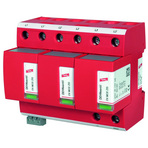
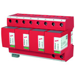
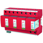
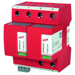
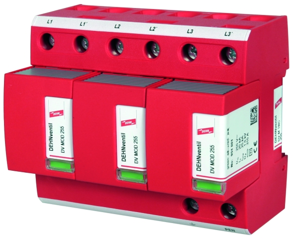
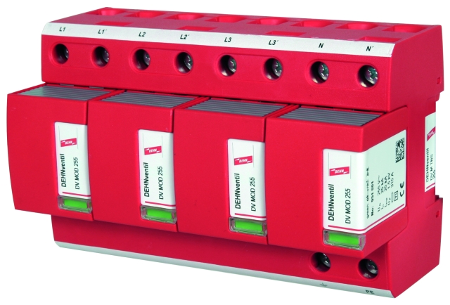
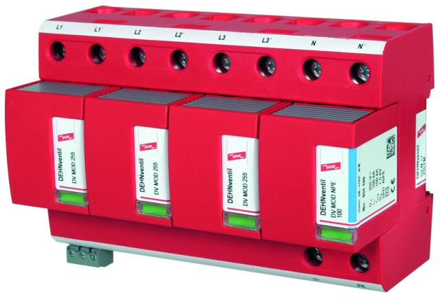
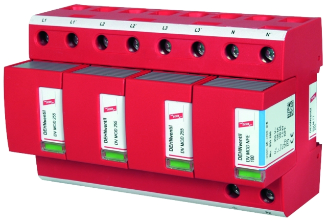
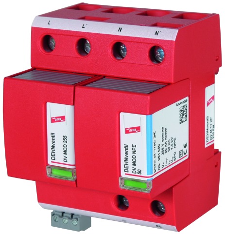
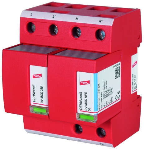
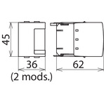
DEHNventil® modular

Modular multipole Combined Lightning Current and Surge Arrester

For protecting low-voltage consumer's installations against surges and even direct lightning strikes. For installation in conformity with the lightning protection zone concept at the boundaries from 0A– 2.
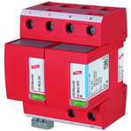
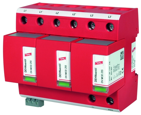
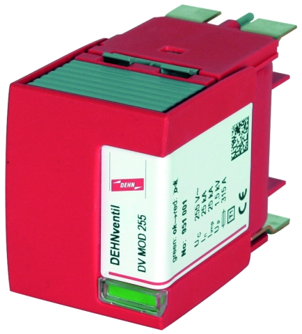
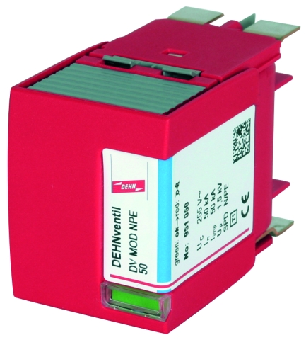
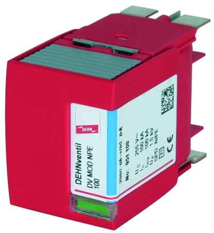
  • Prewired spark-gap-based type 1 and type 2 combined lightning current and surge arrester consisting of a base part and plug-in protection modules
  • Maximum system availability due to RADAX Flow follow current limitation
  • No tripping of 20 A gG fuses up to short-circuit currents of 50 kArms
  • Discharge capacity up to 100 kA (10/350 µs)
  • Capable of protecting terminal equipment
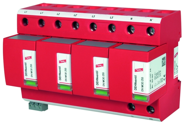
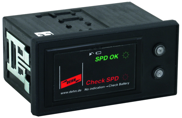
  • Operating state / fault indication by green / red indicator flag in the inspection window
  • Easy replacement of protection modules without tools due to module locking system with module release button
  • Vibration and shock-tested according to EN 60068-2

Version

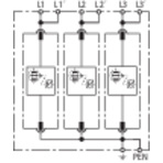
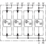
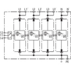
DEHNventil M TNC 255: Modular combined lightning current and surge arrester for use in TN-C systems
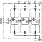
DEHNventil M TNS 255: Modular combined lightning current and surge arrester for use in TN-S systems
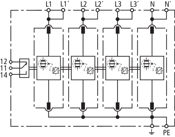
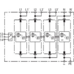
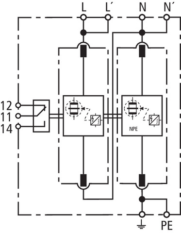
DEHNventil M TT 255: Modular combined lightning current and surge arrester for use in TT and TN-S systems (3+1 configuration)
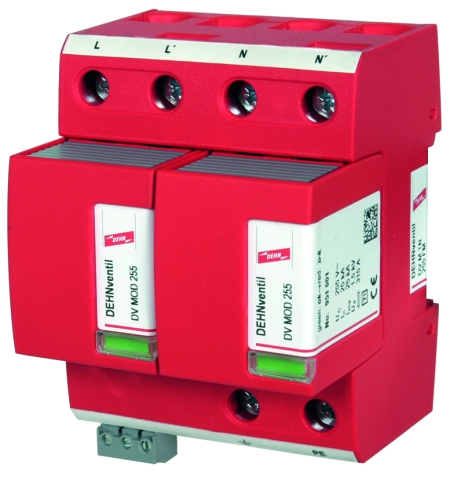
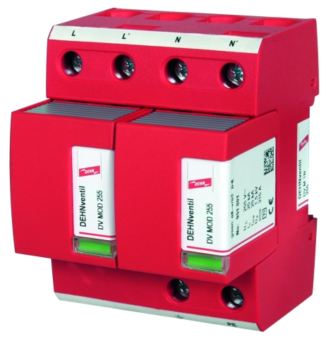
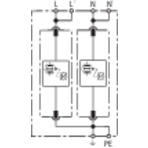
DEHNventil M TN 255: Modular combined lightning current and surge arrester for use in single-phase TN systems
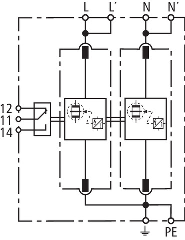
DEHNventil M TT 2P 255: Modular combined lightning current and surge arrester for use in single-phase TT and TN systems (1+1 configuration)
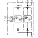
DEHNventil M ... FM: With remote signalling contact for monitoring device (floating changeover contact)

Details

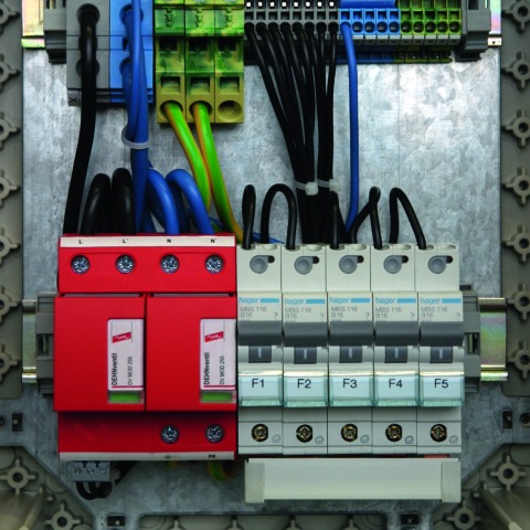
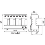
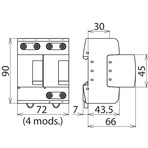
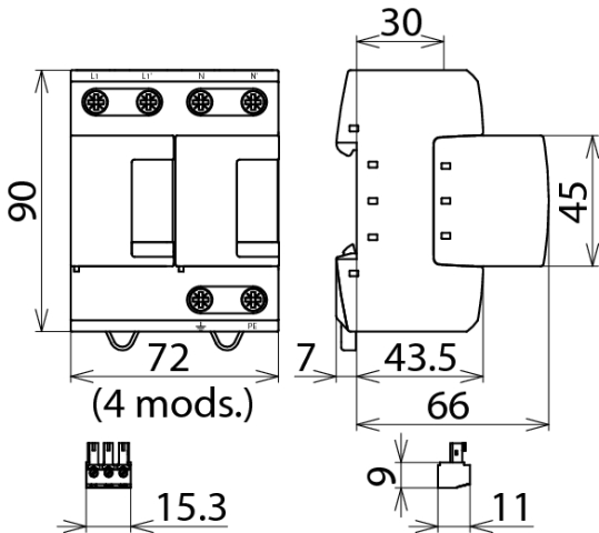
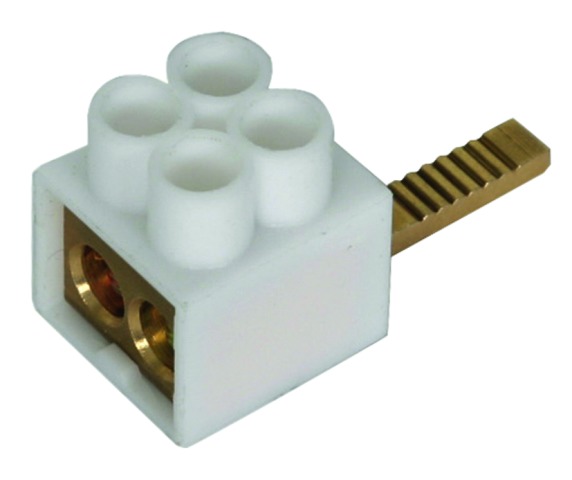
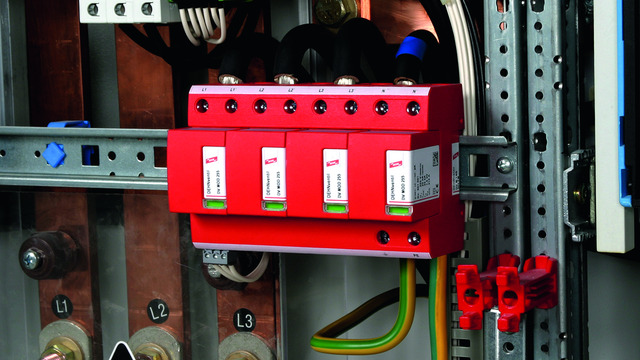
With their functional Red/Line design, the devices of the modular DEHNventil family provide a combination of safety and innovation. Designed for "all-in-one installation", the arresters integrate lightning equipotential bonding and surge protection in a single device, making them ideal for use in compact electrical installations. The energy-coordinated arresters even allow to protect terminal equipment if the distance between DEHNventil and the loads is ≤ 10 m. With a lightning current discharge capacity up to 100,000 A, the arresters ensure a high degree of availability of the electrical installation to be protected. Even in large-scale electrical installations, the modular DEHNventil arresters provide various application benefits. The Red/Line surge arresters installed at the boundaries of the individual lightning protection zones, for example, are already energy-coordinated with the DEHNventil arresters. Encapsulated creepage discharge spark gaps and the small space requirements enable easy integration into switchgear installations or distribution boards. A special feature of the modular DEHNventil family is its functional design, in particular the module locking system. It fixes the protection module firmly in place so that it is safely connected to the base part even with maximum loads. If a protection module has to be replaced, it releases the module without tools and allows easy removal. By using the double terminals suitable for all conductors, the arresters can be connected in series in a space-saving and cost-effective way up to nominal currents of 125 A as preferred by IEC 60364-5-53. Busbars of type MVS 3 8 6 and MVS 4 11 8 can be used for connecting further DIN rail mounted devices. The type designation of DEHNventil arresters allows to easily choose the right arrester for the relevant system configuration of the low-voltage consumer’s installation.

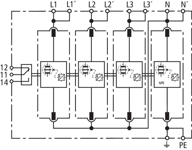
The patented RADAX Flow technology for follow current limitation and extinction allows high availability of the electrical consumer's installation to be protected. Even in case of short-circuit currents as high as 100 kArms, mains follow currents are reduced in such a way that selectivity with respect to low-current-rated fuses is ensured. This means that upstream fuses will not trip due to upcoming mains follow currents.

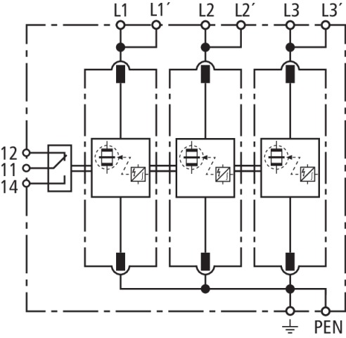
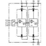
The operating state / fault indicator of each protective path needs no power to operate and instantly shows the operating state of the surge arrester. Apart from the standard visual indicator with green and red indicator flags, DEHNventil M ... FM devices feature a three-pole remote signalling terminal. With its floating changeover contact, the remote signal can be used as a break or make contact according to the particular circuit concept.

Due to their parameters and design, the devices can be even installed upstream of meter panels in low-voltage consumer's installations.

Models

DEHNventil M TNC (FM)

DEHNventil M TNS (FM)

DEHNventil M TT (FM)

DEHNventil M TN (FM)

DEHNventil M TT 2P (FM)

DEHNventil M TNC (FM)

Basic circuit diagram DV M TNC 255 FMDimension drawing DV M TNC 255 FM

Modular combined lightning current and surge arrester for TN-C systems with a nominal voltage of 230 / 400 V (3+0 configuration); FM version with floating remote signalling contact.


Specifications

Type
Part No.
SPD according to EN 61643-11 / IEC 61643-11
Energy coordination with terminal equipment (≤ 10 m)
Nominal voltage (a.c.) (UN)
Max. continuous operating voltage (a.c.) (UC)
Lightning impulse current (10/350 µs) [L1+L2+L3-PEN] (Itotal)
Specific energy [L1+L2+L3-PEN] (W/R)
Lightning impulse current (10/350 µs) [L-PEN] (Iimp)
Specific energy [L-PEN] (W/R)
Nominal discharge current (8/20 µs) [L-PEN]/[L1+L2+L3-PEN] (In)
Voltage protection level (UP)
Follow current extinguishing capability (a.c.) (Ifi)
Follow current limitation / Selectivity
Response time (tA)
Max. backup fuse (L) up to IK = 50 kArms
Max. backup fuse (L-L')
Temporary overvoltage (TOV) (UT) – Characteristic
Operating temperature range [parallel] / [series] (TU)
Operating state / fault indication
Number of ports
Cross-sectional area (L1, L1', L2, L2', L3, L3', PEN, 9) (min.)
Cross-sectional area (L1, L2, L3, PEN) (max.)
Cross-sectional area (L1', L2', L3', 9) (max.)
For mounting on
Enclosure material
Place of installation
Degree of protection
Capacity
Approvals
Type of remote signalling contact
Switching capacity (a.c.)
Switching capacity (d.c.)
Cross-sectional area for remote signalling terminals
Extended technical data:
– Max. prospective short-circuit current
– Limitation / Extinction of mains follow currents
– Max. backup fuse (L) up to IK = 100 kArms
Weight
GTIN
PU
Part No.
  • DV M TNC 255
  • 951 300
  • type 1 + type 2 / class I + class II
  • type 1 + type 2 + type 3
  • 230 / 400 V (50 / 60 Hz)
  • 264 V (50 / 60 Hz)
  • 75 kA
  • 1.40 MJ/ohms
  • 25 kA
  • 156.25 kJ/ohms
  • 25 / 75 kA
  • 1.5 kV
  • 50 kArms
  • no tripping of a 20 A gG fuse up to 50 kArms (prosp.)
  • ≤ 100 ns
  • 315 A gG
  • 125 A gG
  • 440 V / 120 min. – withstand
  • -40 °C ... +80 °C / -40 °C ... +60 °C
  • green / red
  • 1
  • 10 mm2 solid / flexible
  • 50 mm2 stranded / 35 mm2 flexible
  • 35 mm2 stranded / 25 mm2 flexible
  • 35 mm DIN rails acc. to EN 60715
  • thermoplastic, red, UL 94 V-0
  • indoor installation
  • IP 20
  • 6 module(s), DIN 43880
  • KEMA, VDE, UL
  •  
  •  
  •  
  •  
  • For use in switchgear installations with prospective short-circuit currents of more than 50 kArms (tested by the German VDE)
  • 100 kArms (220 kApeak)
  • up to 100 kArms (220 kApeak)
  • 315 A gG
  • 970 g
  • 4013364108134
  • 1 pc(s)
  • 951 300
  • Specifications (PDF)
  • More
  • DV M TNC 255 FM
  • 951 305
  • type 1 + type 2 / class I + class II
  • type 1 + type 2 + type 3
  • 230 / 400 V (50 / 60 Hz)
  • 264 V (50 / 60 Hz)
  • 75 kA
  • 1.40 MJ/ohms
  • 25 kA
  • 156.25 kJ/ohms
  • 25 / 75 kA
  • ≤ 1.5 kV
  • 50 kArms
  • no tripping of a 20 A gG fuse up to 50 kArms (prosp.)
  • ≤ 100 ns
  • 315 A gG
  • 125 A gG
  • 440 V / 120 min. – withstand
  • -40 °C ... +80 °C / -40 °C ... +60 °C
  • green / red
  • 1
  • 10 mm2 solid / flexible
  • 50 mm2 stranded / 35 mm2 flexible
  • 35 mm2 stranded / 25 mm2 flexible
  • 35 mm DIN rails acc. to EN 60715
  • thermoplastic, red, UL 94 V-0
  • indoor installation
  • IP 20
  • 6 module(s), DIN 43880
  • KEMA, VDE, UL
  • changeover contact
  • 250 V / 0.5 A
  • 250 V / 0.1 A; 125 V / 0.2 A; 75 V / 0.5 A
  • max. 1.5 mm2 solid / flexible
  • For use in switchgear installations with prospective short-circuit currents of more than 50 kArms (tested by the German VDE)
  • 100 kArms (220 kApeak)
  • up to 100 kArms (220 kApeak)
  • 315 A gG
  • 962 g
  • 4013364108141
  • 1 pc(s)
  • 951 305
  • Specifications (PDF)
  • More

DEHNventil M TNS (FM)

Basic circuit diagram DV M TNS 255 FMDimension drawing DV M TNS 255 FM

Modular combined lightning current and surge arrester for TN-S systems with a nominal voltage of 230 / 400 V (4+0 configuration); FM version with floating remote signalling contact.


Specifications

Type
Part No.
SPD according to EN 61643-11 / IEC 61643-11
Energy coordination with terminal equipment (≤ 10 m)
Nominal voltage (a.c.) (UN)
Max. continuous operating voltage (a.c.) (UC)
Lightning impulse current (10/350 µs) [L1+L2+L3+N-PE] (Itotal)
Specific energy [L1+L2+L3+N-PE] (W/R)
Lightning impulse current (10/350 µs) [L, N-PE] (Iimp)
Specific energy [L,N-PE] (W/R)
Nominal discharge current (8/20 µs) [L/N-PE]/[L1+L2+L3+N-PE] (In)
Voltage protection level [L-PE]/[N-PE] (UP)
Follow current extinguishing capability (a.c.) (Ifi)
Follow current limitation / Selectivity
Response time (tA)
Max. backup fuse (L) up to IK = 50 kArms
Max. backup fuse (L-L')
Temporary overvoltage (TOV) [L-N] (UT) – Characteristic
Operating temperature range [parallel] / [series] (TU)
Operating state / fault indication
Number of ports
Cross-sectional area (L1, L1', L2, L2', L3, L3', N, N', PE, 9) (min.)
Cross-sectional area (L1, L2, L3, N, PE) (max.)
Cross-sectional area (L1', L2', L3', N', 9) (max.)
For mounting on
Enclosure material
Place of installation
Degree of protection
Capacity
Approvals
Type of remote signalling contact
Switching capacity (a.c.)
Switching capacity (d.c.)
Cross-sectional area for remote signalling terminals
Extended technical data:
– Max. prospective short-circuit current
– Limitation / Extinction of mains follow currents
– Max. backup fuse (L) up to IK = 100 kArms
Weight
GTIN
PU
Part No.
  • DV M TNS 255
  • 951 400
  • type 1 + type 2 / class I + class II
  • type 1 + type 2 + type 3
  • 230 / 400 V (50 / 60 Hz)
  • 264 V (50 / 60 Hz)
  • 100 kA
  • 2.50 MJ/ohms
  • 25 kA
  • 156.25 kJ/ohms
  • 25 / 100 kA
  • ≤ 1.5 / ≤ 1.5 kV
  • 50 kArms
  • no tripping of a 20 A gG fuse up to 50 kArms (prosp.)
  • ≤ 100 ns
  • 315 A gG
  • 125 A gG
  • 440 V / 120 min. – withstand
  • -40 °C ... +80 °C / -40 °C ... +60 °C
  • green / red
  • 1
  • 10 mm2 solid / flexible
  • 50 mm2 stranded / 35 mm2 flexible
  • 35 mm2 stranded / 25 mm2 flexible
  • 35 mm DIN rails acc. to EN 60715
  • thermoplastic, red, UL 94 V-0
  • indoor installation
  • IP 20
  • 8 module(s), DIN 43880
  • KEMA, VDE, UL
  •  
  •  
  •  
  •  
  • For use in switchgear installations with prospective short-circuit currents of more than 50 kArms (tested by the German VDE)
  • 100 kArms (220 kApeak)
  • up to 100 kArms (220 kApeak)
  • 315 A gG
  • 1,35 kg
  • 4013364108158
  • 1 pc(s)
  • 951 400
  • Specifications (PDF)
  • More
  • DV M TNS 255 FM
  • 951 405
  • type 1 + type 2 / class I + class II
  • type 1 + type 2 + type 3
  • 230 / 400 V (50 / 60 Hz)
  • 264 V (50 / 60 Hz)
  • 100 kA
  • 2.50 MJ/ohms
  • 25 kA
  • 156.25 kJ/ohms
  • 25 / 100 kA
  • ≤ 1.5 / ≤ 1.5 kV
  • 50 kArms
  • no tripping of a 20 A gG fuse up to 50 kArms (prosp.)
  • ≤ 100 ns
  • 315 A gG
  • 125 A gG
  • 440 V / 120 min. – withstand
  • -40 °C ... +80 °C / -40 °C ... +60 °C
  • green / red
  • 1
  • 10 mm2 solid / flexible
  • 50 mm2 stranded / 35 mm2 flexible
  • 35 mm2 stranded / 25 mm2 flexible
  • 35 mm DIN rails acc. to EN 60715
  • thermoplastic, red, UL 94 V-0
  • indoor installation
  • IP 20
  • 8 module(s), DIN 43880
  • KEMA, VDE, UL
  • changeover contact
  • 250 V / 0.5 A
  • 250 V / 0.1 A; 125 V / 0.2 A; 75 V / 0.5 A
  • max. 1.5 mm2 solid / flexible
  • For use in switchgear installations with prospective short-circuit currents of more than 50 kArms (tested by the German VDE)
  • 100 kArms (220 kApeak)
  • up to 100 kArms (220 kApeak)
  • 315 A gG
  • 1,36 kg
  • 4013364108165
  • 1 pc(s)
  • 951 405
  • Specifications (PDF)
  • More

DEHNventil M TT (FM)

Basic circuit diagram DV M TT 255 FMDimension drawing DV M TT 255 FM

Modular combined lightning current and surge arrester for TT and TN-S systems with a nominal voltage of 230 / 400 V (3+1 configuration); FM version with floating remote signalling contact.


Specifications

Type
Part No.
SPD according to EN 61643-11 / IEC 61643-11
Energy coordination with terminal equipment (≤ 10 m)
Nominal voltage (a.c.) (UN)
Max. continuous operating voltage (a.c.) [L-N] (UC)
Max. continuous operating voltage (a.c.) [N-PE] (UC (N-PE))
Lightning impulse current (10/350 µs) [L1+L2+L3+N-PE] (Itotal)
Specific energy [L1+L2+L3+N-PE] (W/R)
Lightning impulse current (10/350 µs) [L-N]/[N-PE] (Iimp)
Specific energy [L-N]/[N-PE] (W/R)
Nominal discharge current (8/20 µs) [L-N]/[N-PE] (In)
Voltage protection level [L-N]/[N-PE] (UP)
Follow current extinguishing capability [L-N]/[N-PE] (Ifi)
Follow current limitation / Selectivity
Response time (tA)
Max. backup fuse (L) up to IK = 50 kArms
Max. backup fuse (L-L')
Temporary overvoltage (TOV) [L-N] (UT) – Characteristic
Temporary overvoltage (TOV) [N-PE] (UT) – Characteristic
Operating temperature range [parallel] / [series] (TU)
Operating state / fault indication
Number of ports
Cross-sectional area (L1, L1', L2, L2', L3, L3', N, N', PE, 9) (min.)
Cross-sectional area (L1, L2, L3, N, PE) (max.)
Cross-sectional area (L1', L2', L3', N', 9) (max.)
For mounting on
Enclosure material
Place of installation / Degree of protection
Place of installation
Degree of protection
Capacity
Approvals
Type of remote signalling contact
Switching capacity (a.c.)
Switching capacity (d.c.)
Cross-sectional area for remote signalling terminals
Extended technical data:
Voltage protection level [L-PE] (UP)
For use in switchgear installations with prospective short-circuit currents of more than 50 kArms (tested by the German VDE)
– Max. prospective short-circuit current
– Limitation / Extinction of mains follow currents
– Max. backup fuse (L) up to IK = 100 kArms
Weight
GTIN
PU
Part No.
  • DV M TT 255
  • 951 310
  • type 1 + type 2 / class I + class II
  • type 1 + type 2 + type 3
  • 230 / 400 V (50 / 60 Hz)
  • 264 V (50 / 60 Hz)
  • 255 V (50 / 60 Hz)
  • 100 kA
  • 2.50 MJ/ohms
  • 25 / 100 kA
  • 156.25 kJ/ohms / 2.50 MJ/ohms
  • 25 / 100 kA
  • ≤ 1.5 / ≤ 1.5 kV
  • 50 kArms / 100 Arms
  • no tripping of a 20 A gG fuse up to 50 kArms (prosp.)
  • ≤ 100 ns
  • 315 A gG
  • 125 A gG
  • 440 V / 120 min. – withstand
  • 1200 V / 200 ms – withstand
  • -40 °C ... +80 °C / -40 °C ... +60 °C
  • green / red
  • 1
  • 10 mm2 solid / flexible
  • 50 mm2 stranded / 35 mm2 flexible
  • 35 mm2 stranded / 25 mm2 flexible
  • 35 mm DIN rails acc. to EN 60715
  • thermoplastic, red, UL 94 V-0
  •  
  • indoor installation
  • IP 20
  • 8 module(s), DIN 43880
  • KEMA, VDE, UL
  •  
  •  
  •  
  •  
  • ---------------------------------
  • 2.2 kV
  • ---------------------------------
  • 100 kArms (220 kApeak)
  • up to 100 kArms (220 kApeak)
  • 315 A gG
  • 1,27 kg
  • 4013364108172
  • 1 pc(s)
  • 951 310
  • Specifications (PDF)
  • More
  • DV M TT 255 FM
  • 951 315
  • type 1 + type 2 / class I + class II
  • type 1 + type 2 + type 3
  • 230 / 400 V (50 / 60 Hz)
  • 264 V (50 / 60 Hz)
  • 255 V (50 / 60 Hz)
  • 100 kA
  • 2.50 MJ/ohms
  • 25 / 100 kA
  • 156.25 kJ/ohms / 2.50 MJ/ohms
  • 25 / 100 kA
  • ≤ 1.5 / ≤ 1.5 kV
  • 50 kArms / 100 Arms
  • no tripping of a 20 A gG fuse up to 50 kArms (prosp.)
  • ≤ 100 ns
  • 315 A gG
  • 125 A gG
  • 440 V / 120 min. – withstand
  • 1200 V / 200 ms – withstand
  • -40 °C ... +80 °C / -40 °C ... +60 °C
  • green / red
  • 1
  • 10 mm2 solid / flexible
  • 50 mm2 stranded / 35 mm2 flexible
  • 35 mm2 stranded / 25 mm2 flexible
  • 35 mm DIN rails acc. to EN 60715
  • thermoplastic, red, UL 94 V-0
  • indoors / IP 20
  •  
  •  
  • 8 module(s), DIN 43880
  • KEMA, VDE, UL
  • changeover contact
  • 250 V / 0.5 A
  • 250 V / 0.1 A; 125 V / 0.2 A; 75 V / 0.5 A
  • max. 1.5 mm2 solid / flexible
  • ---------------------------------
  • 2.2 kV
  • ---------------------------------
  • 100 kArms (220 kApeak)
  • up to 100 kArms (220 kApeak)
  • 315 A gG
  • 1,28 kg
  • 4013364108189
  • 1 pc(s)
  • 951 315
  • Specifications (PDF)
  • More

DEHNventil M TN (FM)

Basic circuit diagram DV M TN 255 FMDimension drawing DV M TN 255 FM

Modular combined lightning current and surge arrester for single-phase TN systems with a nominal voltage of 230 V (2+0 configuration); FM version with floating remote signalling contact.


Specifications

Type
Part No.
SPD according to EN 61643-11 / IEC 61643-11
Energy coordination with terminal equipment (≤ 10 m)
Nominal voltage (a.c.) (UN)
Max. continuous operating voltage (a.c.) (UC)
Lightning impulse current (10/350 µs) [L+N-PE] (Itotal)
Specific energy [L+N-PE] (W/R)
Lightning impulse current (10/350 µs) [L, N-PE] (Iimp)
Specific energy [L,N-PE] (W/R)
Nominal discharge current (8/20 µs) [L/N-PE]/[L+N-PE] (In)
Voltage protection level [L-PE]/[N-PE] (UP)
Follow current extinguishing capability (a.c.) (Ifi)
Follow current limitation / Selectivity
Response time (tA)
Max. backup fuse (L) up to IK = 50 kArms
Max. backup fuse (L-L')
Temporary overvoltage (TOV) [L-N] (UT) – Characteristic
Operating temperature range [parallel] / [series] (TU)
Operating state / fault indication
Number of ports
Cross-sectional area (L, L', N, N', PE, 9) (min.)
Cross-sectional area (L, N, PE) (max.)
Cross-sectional area (L', N', 9) (max.)
For mounting on
Enclosure material
Place of installation
Degree of protection
Capacity
Approvals
Type of remote signalling contact
Switching capacity (a.c.)
Switching capacity (d.c.)
Cross-sectional area for remote signalling terminals
Extended technical data:
– Max. prospective short-circuit current
– Limitation / Extinction of mains follow currents
– Max. backup fuse (L) up to IK = 100 kArms
Weight
GTIN
PU
Part No.
  • DV M TN 255
  • 951 200
  • type 1 + type 2 / class I + class II
  • type 1 + type 2 + type 3
  • 230 V (50 / 60 Hz)
  • 264 V (50 / 60 Hz)
  • 50 kA
  • 625.00 kJ/ohms
  • 25 kA
  • 156.25 kJ/ohms
  • 25 / 50 kA
  • ≤ 1.5 / ≤ 1.5 kV
  • 50 kArms
  • no tripping of a 20 A gG fuse up to 50 kArms (prosp.)
  • ≤ 100 ns
  • 315 A gG
  • 125 A gG
  • 440 V / 120 min. – withstand
  • -40 °C ... +80 °C / -40 °C ... +60 °C
  • green / red
  • 1
  • 10 mm2 solid / flexible
  • 50 mm2 stranded / 35 mm2 flexible
  • 35 mm2 stranded / 25 mm2 flexible
  • 35 mm DIN rails acc. to EN 60715
  • thermoplastic, red, UL 94 V-0
  • indoor installation
  • IP 20
  • 4 module(s), DIN 43880
  • KEMA, VDE, UL
  •  
  •  
  •  
  •  
  • For use in switchgear installations with prospective short-circuit currents of more than 50 kArms (tested by the German VDE)
  • 100 kArms (220 kApeak)
  • up to 100 kArms (220 kApeak)
  • 315 A gG
  • 724 g
  • 4013364108097
  • 1 pc(s)
  • 951 200
  • Specifications (PDF)
  • More
  • DV M TN 255 FM
  • 951 205
  • type 1 + type 2 / class I + class II
  • type 1 + type 2 + type 3
  • 230 V (50 / 60 Hz)
  • 264 V (50 / 60 Hz)
  • 50 kA
  • 625.00 kJ/ohms
  • 25 kA
  • 156.25 kJ/ohms
  • 25 / 50 kA
  • ≤ 1.5 / ≤ 1.5 kV
  • 50 kArms
  • no tripping of a 20 A gG fuse up to 50 kArms (prosp.)
  • ≤ 100 ns
  • 315 A gG
  • 125 A gG
  • 440 V / 120 min. – withstand
  • -40 °C ... +80 °C / -40 °C ... +60 °C
  • green / red
  • 1
  • 10 mm2 solid / flexible
  • 50 mm2 stranded / 35 mm2 flexible
  • 35 mm2 stranded / 25 mm2 flexible
  • 35 mm DIN rails acc. to EN 60715
  • thermoplastic, red, UL 94 V-0
  • indoor installation
  • IP 20
  • 4 module(s), DIN 43880
  • KEMA, VDE, UL
  • changeover contact
  • 250 V / 0.5 A
  • 250 V / 0.1 A; 125 V / 0.2 A; 75 V / 0.5 A
  • max. 1.5 mm2 solid / flexible
  • For use in switchgear installations with prospective short-circuit currents of more than 50 kArms (tested by the German VDE)
  • 100 kArms (220 kApeak)
  • up to 100 kArms (220 kApeak)
  • 315 A gG
  • 668 g
  • 4013364108103
  • 1 pc(s)
  • 951 205
  • Specifications (PDF)
  • More

DEHNventil M TT 2P (FM)

Basic circuit diagram DV M TT 2P 255 FMDimension drawing DV M TT 2P 255 FM

Modular combined lightning current and surge arrester for single-phase TT and TN-S systems with a nominal voltage of 230 V (1+1 configuration); FM version with floating remote signalling contact.


Specifications

Type
Part No.
SPD according to EN 61643-11 / IEC 61643-11
Energy coordination with terminal equipment (≤ 10 m)
Nominal voltage (a.c.) (UN)
Max. continuous operating voltage (a.c.) [L-N] (UC)
Max. continuous operating voltage (a.c.) [N-PE] (UC (N-PE))
Lightning impulse current (10/350 µs) [L+N-PE] (Itotal)
Specific energy [L+N-PE] (W/R)
Lightning impulse current (10/350 µs) [L-N]/[N-PE] (Iimp)
Specific energy [L-N]/[N-PE] (W/R)
Nominal discharge current (8/20 µs) [L-N]/[N-PE] (In)
Voltage protection level [L-N]/[N-PE] (UP)
Follow current extinguishing capability [L-N]/[N-PE] (Ifi)
Follow current limitation / Selectivity
Response time (tA)
Max. backup fuse (L) up to IK = 50 kArms
Max. backup fuse (L-L')
Temporary overvoltage (TOV) [L-N] (UT) – Characteristic
Temporary overvoltage (TOV) [N-PE] (UT) – Characteristic
Operating temperature range [parallel] / [series] (TU)
Operating state / fault indication
Number of ports
Cross-sectional area (L, L', N, N', PE, 9) (min.)
Cross-sectional area (L, N, PE) (max.)
Cross-sectional area (L', N', 9) (max.)
For mounting on
Enclosure material
Place of installation / Degree of protection
Place of installation
Degree of protection
Capacity
Approvals
Type of remote signalling contact
Switching capacity (a.c.)
Switching capacity (d.c.)
Cross-sectional area for remote signalling terminals
Extended technical data:
Voltage protection level [L-PE] (UP)
For use in switchgear installations with prospective short-circuit currents of more than 50 kArms (tested by the German VDE)
– Max. prospective short-circuit current
– Limitation / Extinction of mains follow currents
– Max. backup fuse (L) up to IK = 100 kArms
Weight
GTIN
PU
Part No.
  • DV M TT 2P 255
  • 951 110
  • type 1 + type 2 / class I + class II
  • type 1 + type 2 + type 3
  • 230 V (50 / 60 Hz)
  • 264 V (50 / 60 Hz)
  • 255 V (50 / 60 Hz)
  • 50 kA
  • 625.00 kJ/ohms
  • 25 / 50 kA
  • 156.25 / 625.00 kJ/ohms
  • 25 / 50 kA
  • ≤ 1.5 / ≤ 1.5 kV
  • 50 kArms / 100 Arms
  • no tripping of a 20 A gG fuse up to 50 kArms (prosp.)
  • ≤ 100 ns
  • 315 A gG
  • 125 A gG
  • 440 V / 120 min. – withstand
  • 1200 V / 200 ms – withstand
  • -40 °C ... +80 °C / -40 °C ... +60 °C
  • green / red
  • 1
  • 10 mm2 solid / flexible
  • 50 mm2 stranded / 35 mm2 flexible
  • 35 mm2 stranded / 25 mm2 flexible
  • 35 mm DIN rails acc. to EN 60715
  • thermoplastic, red, UL 94-V-0
  •  
  • indoor installation
  • IP 20
  • 4 module(s), DIN 43880
  • KEMA, VDE, UL
  •  
  •  
  •  
  •  
  • ---------------------------------
  • 2.2 kV
  • ---------------------------------
  • 100 kArms (220 kApeak)
  • up to 100 kArms (220 kApeak)
  • 315  A gG
  • 659 g
  • 4013364108110
  • 1 pc(s)
  • 951 110
  • Specifications (PDF)
  • More
  • DV M TT 2P 255 FM
  • 951 115
  • type 1 + type 2 / class I + class II
  • type 1 + type 2 + type 3
  • 230 V (50 / 60 Hz)
  • 264 V (50 / 60 Hz)
  • 255 V (50 / 60 Hz)
  • 50 kA
  • 625.00 kJ/ohms
  • 25 / 50 kA
  • 156.25 / 625.00 kJ/ohms
  • 25 / 50 kA
  • ≤ 1.5 / ≤ 1.5 kV
  • 50 kArms / 100 Arms
  • no tripping of a 20 A gG fuse up to 50 kArms (prosp.)
  • ≤ 100 ns
  • 315 A gG
  • 125 A gG
  • 440 V / 120 min. – withstand
  • 1200 V / 200 ms – withstand
  • -40 °C ... +80 °C / -40 °C ... +60 °C
  • green / red
  • 1
  • 10 mm2 solid / flexible
  • 50 mm2 stranded / 35 mm2 flexible
  • 35 mm2 stranded / 25 mm2 flexible
  • 35 mm DIN rails acc. to EN 60715
  • thermoplastic, red, UL 94-V-0
  • indoors / IP 20
  •  
  •  
  • 4 module(s), DIN 43880
  • KEMA, VDE, UL
  • changeover contact
  • 250 V / 0.5 A
  • 250 V / 0.1 A; 125 V / 0.2 A; 75 V / 0.5 A
  • max. 1.5 mm2 solid / flexible
  • ---------------------------------
  • 2.2 kV
  • ---------------------------------
  • 100 kArms (220 kApeak)
  • up to 100 kArms (220 kApeak)
  • 315 A gG
  • 664 g
  • 4013364108127
  • 1 pc(s)
  • 951 115
  • Specifications (PDF)
  • More

Accessories

DEHNpanel

Visual remote indicator for (multiple) surge protective devices (SPDs)

Show SpecificationsHide Specifications

Specifications

Type
Part No.
Operating state/fault indication
Enclosure material
Weight
GTIN
PU
  • DPAN L
  • 910 200
  • green LED (flashing) / red LED (flashing)
  • noryl
  • 140 g
  • 4013364144019
  • 1 pc(s)
  • Specifications (PDF)
  • More
    • Further Pictures
      open PDF
      Further Information
      Product Specifications (Text)

      Back

      DPAN L visual remote indication for surge protective devices
      Visual remote indicator with current-saving LEDs for surge protective devices (SPDs) 
      With remote signalling contact
      Also suited for alarm signalling of other devices with floating changeover contact
      For installation in switchgear cabinet doors.
      Power supply: 2x 1.5 V AA batteries
      Degree of protection: IP 40
      Mounting dimensions: 92 x 45 mm
      Dimensions: 96 x 48 x 75 mm

      delivery and installation.

      Brand: DEHN
      Type: DPAN L
      Part No.: 910 200

      or equivalent.
      Installation Instructions
      Certificates
      CE_DEHNpanel

Spark-Gap-Based Protection Module

Spark-gap-based protection module for DEHNventil M ...

Show SpecificationsHide Specifications

Specifications

Type
Part No.
Max. continuous operating voltage (a.c.) (UC)
Weight
GTIN
PU
  • DV MOD 255
  • 951 001
  • 264 V
  • 192 g
  • 4013364108066
  • 1 pc(s)
  • Specifications (PDF)
  • More
    • Further Pictures
      open PDF
      Further Information
      Product Specifications (Text)

      Back

      DV MOD 255 spark-gap-based protection module
      Spark-gap-based protection module for type 1 + type 2
      arresters of the Red/Line series acc. to EN 61643-11
      Heavy-duty creepage discharge spark gap
      Fault indication by green and red indicator
      flag in the inspection window
      Max. continuous operating voltage: 264 V a.c.
      Lightning impulse current: 50 kA (prosp.)
      

      delivery and installation.

      Brand: DEHN
      Type: DV MOD 255
      Part No.: 951 001

      or equivalent.
      Installation Instructions
      Certificates
      CE_DV_M_TN_255_FM
      CE_DV_M_TNC_255_FM

N-PE Spark-Gap-Based Protection Module

N-PE spark-gap-based protection module for DEHNventil M ... with ...+1 configuration.

Show SpecificationsHide Specifications

Specifications

Type
Part No.
Max. continuous operating voltage (a.c.) (UC)
Weight
GTIN
PU

STAK 2X16 Pin-shaped Terminal

Allows to connect cross-sections that are smaller than the specified minimum terminal cross section of the surge protective device

Show SpecificationsHide Specifications

Specifications

Type
Part No.
Lightning impulse current (10/350 µs)
Cross-sectional area (min.)
Cross-sectional area (max.)
Type of connection
Weight
GTIN
PU
  • STAK 2X16
  • 900 589
  • 25 kA
  • 2x 1,5 mm2
  • 2x max. 16 mm2
  • front (double terminal)
  • 20 g
  • 4013364109339
  • 1 pc(s)
  • Specifications (PDF)
  • More
    • Further Pictures
      Further Information
      Product Specifications (Text)

      Back

      STAK 2X16 pin-shaped terminal
      Double terminal for serial connection
      Cross-sectional area:		2 x 16 mm²


      delivery and installation.

      Brand: DEHN
      Type: STAK 2X16
      Part No.: 900 589

      or equivalent.