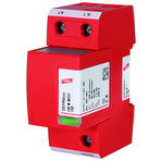
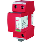
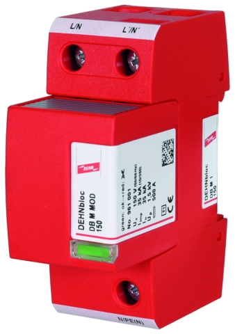
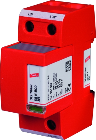
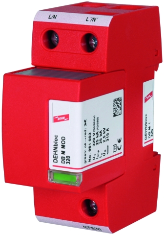
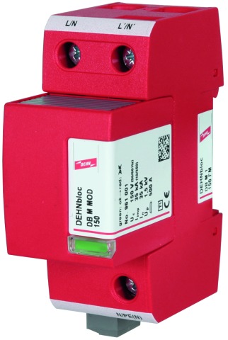
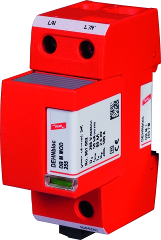
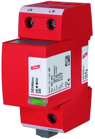
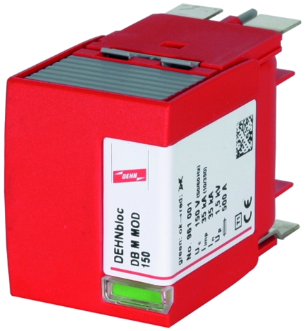
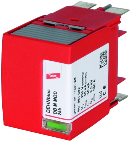
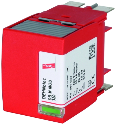
DEHNbloc® modular

Coordinated and modular single-pole Lightning Current Arrester

For protecting low-voltage consumer's installations against surges and even direct lightning strikes. For installation in conformity with the lightning protection zone concept at the boundaries from 0A– 1.
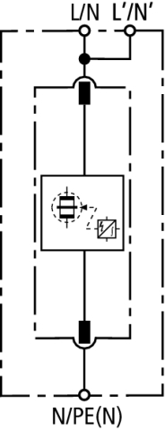
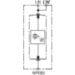
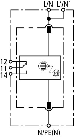
  • Coordinated spark-gap-based lightning current arrester consisting of a base part and a plug-in protection module
  • Maximum system availability due to RADAX Flow follow current limitation
  • No tripping of 32 A gG fuses up to short-circuit currents of 50 kArms
  • Discharge capacity up to 50 kA (10/350 µs)
  • Directly coordinated with DEHNguard surge protective devices without additional cable length
  • Low voltage protection level
  • Operating state / fault indication by green / red indicator flag in the inspection window
  • Easy replacement of protection modules without tools due to module locking system with module release button

Version

DEHNbloc M 1 ...: Coordinated and modular single-pole lightning current arrester with high follow current limitation
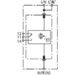
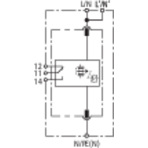
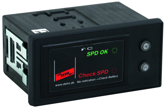
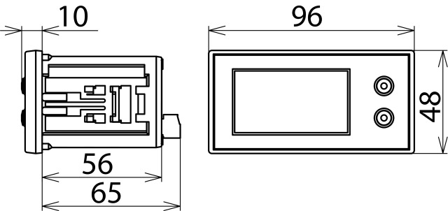
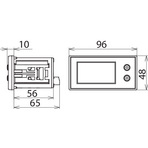
DEHNbloc M 1 ... FM: With remote signalling contact for monitoring device (floating changeover contact)

Details

The modular devices of the DEHNbloc M product family are coordinated lightning current arresters with a functional design.

Energy coordination with type 2 surge arresters of the DEHNguard family is ensured without additional cable lengths or decoupling coils. This is one of the most important features of the Red/Line product families.

The DEHNbloc M arresters combine high performance and ease of use in a single device. Their electrical parameters are rated for the most stringent requirements within lightning and surge protection systems. DEHNbloc M is ideally suited for use in the main distribution board of the low-voltage consumer´s installation of a building. Equipped with the latest RADAX Flow spark gap technology, the protection and availability of electrical installations is a top priority of DEHNbloc M.

Due to the unique follow current limitation and extinction, fuses are not tripped by follow currents even in case of low-current-rated fuses in the installation. The leakage-current-free protective circuit and the mechanical operating state indicator allow the device to be installed even in areas upstream of meter panels in low-voltage consumer's installations.

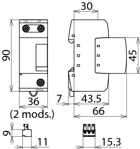
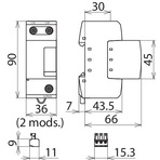
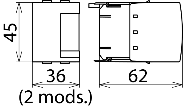
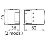
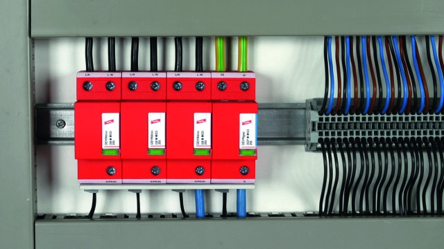
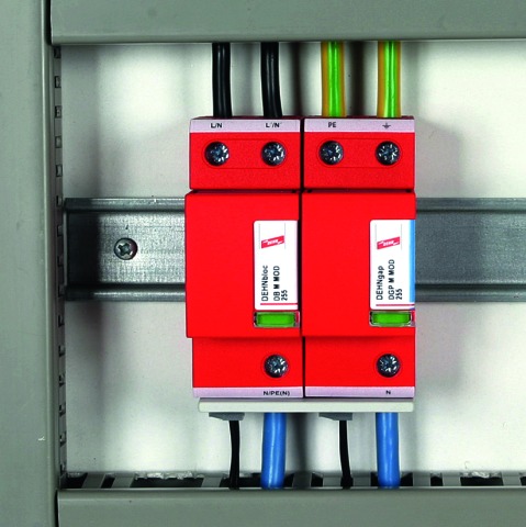
The modular design of the DEHNbloc M arresters makes them safe and easy to use. Their vibration-proof module locking system, for example, is unique. Shock or vibration during transport or operation or enormous mechanical impulse loads resulting from discharges do not affect the module locking system which ensures safe fixation both for the base part and protection module. Nevertheless, the protection modules can be easily replaced without tools by simply pressing the easy-to-use module release button. Both the base part and protection module are mechanically coded to ensure against installing an incorrect module. DEHNbloc M devices incorporate double terminals, allowing series connection of the arresters in a space-saving and cost-effective way according to IEC 60364-5-53 requirements for nominal currents up to 125 A.

The operating state / fault indicator of DEHNbloc M needs no power to operate and instantly shows the operating state of the device. Apart from the standard visual indicator with red and green indicator flags, DEHNbloc M ... FM devices feature an additional remote signalling output. With its floating changeover contact, the remote signal can be used as a break or make contact according to the particular circuit concept.

Models

DEHNbloc M 1 ...

DEHNbloc M 1 ... FM

DEHNbloc M 1 ...

Basic circuit diagram DB M 1 ...Dimension drawing DB M 1 ...

Coordinated and modular single-pole lightning current arrester with a high discharge capacity.


Specifications

Type
Part No.
SPD according to EN 61643-11 / IEC 61643-11
Nominal voltage (a.c.) (UN)
Max. continuous operating voltage (a.c.) (UC)
Lightning impulse current (10/350 µs) (Iimp)
Specific energy (W/R)
Voltage protection level (UP)
Follow current extinguishing capability (a.c.) (Ifi)
Follow current limitation / Selectivity
Response time (tA)
Max. backup fuse (L) up to IK = 50 kArms (ta ≤ 0.2 s)
Max. backup fuse (L) up to IK = 50 kArms (ta ≤ 5 s)
Max. backup fuse (L) for IK > 50 kArms
Max. backup fuse (L) up to IK = 35 kArms (ta ≤ 0.2 s)
Max. backup fuse (L) up to IK = 35 kArms (ta ≤ 5 s)
Max. backup fuse (L) for IK > 35 kArms
Max. backup fuse (L-L')
Temporary overvoltage (TOV) (UT) – Characteristic
Operating temperature range (parallel connection) (TUP)
Operating temperature range (series connection) (TUS)
Operating state / fault indication
Number of ports
Cross-sectional area (L/N, L'/N', N/PE (N)) (min.)
Cross-sectional area (L/N, N/PE(N)) (max.)
Cross-sectional area (L'/N') (max.)
For mounting on
Enclosure material
Place of installation
Degree of protection
Capacity
Approvals
Extended technical data:
– Max. prospective short-circuit current
– Limitation / Extinction of mains follow currents
– Max. backup fuse (L) up to IK = 100 kArms (ta ≤ 0.2 s)
– Max. backup fuse (L) up to IK = 100 kArms (ta ≤ 5 s)
Supplementary data:
– Nominal discharge current (8/20 µs) (In)
Weight
GTIN
PU
Part No.
  • DB M 1 150
  • 961 110
  • type 1 / class I
  • 120 V (50 / 60 Hz)
  • 150 V (50 / 60 Hz)
  • 35 kA
  • 306.25 kJ/ohms
  • ≤ 1.5 kV
  • 35 kArms
  • no tripping of a 32 A gG fuse up to 35 kArms (prosp.)
  • ≤ 100 ns
  •  
  •  
  •  
  • 500 A gG
  • 315 A gG
  • 200 A gG
  • 125 A gG
  • 230 V / 120 min. – withstand
  • -40 °C ... +80 °C
  • -40 °C ... +60 °C
  • green / red
  • 1
  • 10 mm2 solid / flexible
  • 50 mm2 stranded / 35 mm2 flexible
  • 35 mm2 stranded / 25 mm2 flexible
  • 35 mm DIN rails acc. to EN 60715
  • thermoplastic, red, UL 94 V-0
  • indoor installation
  • IP 20
  • 2 module(s), DIN 43880
  • UL, CSA
  •  
  •  
  •  
  •  
  •  
  •  
  •  
  • 317 g
  • 4013364118560
  • 1 pc(s)
  • 961 110
  • Specifications (PDF)
  • More
  • DB M 1 255
  • 961 120
  • type 1 / class I
  • 230 V (50 / 60 Hz)
  • 255 V (50 / 60 Hz)
  • 50 kA
  • 625.00 kJ/ohms
  • ≤ 2.5 kV
  • 50 kArms
  • no tripping of a 32 A gG fuse up to 50 kArms (prosp.)
  • ≤ 100 ns
  • 500 A gG
  • 315 A gG
  •  
  •  
  •  
  •  
  • 125 A gG
  • 440 V / 120 min. – withstand
  • -40 °C ... +80 °C
  • -40 °C ... +60 °C
  • green / red
  • 1
  • 10 mm2 solid / flexible
  • 50 mm2 stranded / 35 mm2 flexible
  • 35 mm2 stranded / 25 mm2 flexible
  • 35 mm DIN rails acc. to EN 60715
  • thermoplastic, red, UL 94 V-0
  • indoor installation
  • IP 20
  • 2 module(s), DIN 43880
  • VDE, KEMA, UL
  • Use in switchgear installations with prospective short-circuit currents of more than 50 kArms (tested by the German VDE)
  • 100 kArms (220 kApeak)
  • up to 100 kArms (220 kApeak)
  • 500 A gG
  • 315  A gG
  • --------------------
  • 50 kA
  • 340 g
  • 4013364118614
  • 1 pc(s)
  • 961 120
  • Specifications (PDF)
  • More
  • DB M 1 320
  • 961 130
  • type 1 / class I
  • 277 V (50 / 60 Hz)
  • 320 V (50 / 60 Hz)
  • 25 kA
  • 156.25 kJ/ohms
  • ≤ 2.5 kV
  • 50 kArms
  • no tripping of a 32 A gG fuse up to 50 kArms (prosp.)
  • ≤ 100 ns
  • 315 A gG
  • 315 A gG
  • 200 A gG
  •  
  •  
  •  
  • 125 A gG
  • 530 V / 120 min. – withstand
  • -40 °C ... +80 °C
  • -40 °C ... +60 °C
  • green / red
  • 1
  • 10 mm2 solid / flexible
  • 50 mm2 stranded / 35 mm2 flexible
  • 35 mm2 stranded / 25 mm2 flexible
  • 35 mm DIN rails acc. to EN 60715
  • thermoplastic, red, UL 94 V-0
  • indoor installation
  • IP 20
  • 2 module(s), DIN 43880
  • UL
  •  
  •  
  •  
  •  
  •  
  •  
  •  
  • 325 g
  • 4013364118638
  • 1 pc(s)
  • 961 130
  • Specifications (PDF)
  • More

DEHNbloc M 1 ... FM

Basic circuit diagram DB M 1 ... FMDimension drawing DB M 1 ... FM

Coordinated and modular single-pole lightning current arrester with a high discharge capacity; with remote signalling contact for monitoring system (floating changeover contact).


Specifications

Type
Part No.
SPD according to EN 61643-11 / IEC 61643-11
Nominal voltage (a.c.) (UN)
Max. continuous operating voltage (a.c.) (UC)
Lightning impulse current (10/350 µs) (Iimp)
Specific energy (W/R)
Voltage protection level (UP)
Follow current extinguishing capability (a.c.) (Ifi)
Follow current limitation / Selectivity
Response time (tA)
Max. backup fuse (L) up to IK = 50 kArms (ta ≤ 0.2 s)
Max. backup fuse (L) up to IK = 50 kArms (ta ≤ 5 s)
Max. backup fuse (L) for IK > 50 kArms
Max. backup fuse (L) up to IK = 35 kArms (ta ≤ 0.2 s)
Max. backup fuse (L) up to IK = 35 kArms (ta ≤ 5 s)
Max. backup fuse (L) for IK > 35 kArms
Max. backup fuse (L-L')
Temporary overvoltage (TOV) (UT) – Characteristic
Operating temperature range (parallel connection) (TUP)
Operating temperature range (series connection) (TUS)
Operating state / fault indication
Number of ports
Cross-sectional area (L/N, L'/N', N/PE (N)) (min.)
Cross-sectional area (L/N, N/PE(N)) (max.)
Cross-sectional area (L'/N') (max.)
For mounting on
Enclosure material
Place of installation
Degree of protection
Capacity
Approvals
Type of remote signalling contact
Switching capacity (a.c.)
Switching capacity (d.c.)
Cross-sectional area for remote signalling terminals
Extended technical data:
– Max. prospective short-circuit current
– Limitation / Extinction of mains follow currents
– Max. backup fuse (L) up to IK = 100 kArms (ta ≤ 0.2 s)
– Max. backup fuse (L) up to IK = 100 kArms (ta ≤ 5 s)
Supplementary data:
– Nominal discharge current (8/20 µs) (In)
Weight
GTIN
PU
Part No.
  • DB M 1 150 FM
  • 961 115
  • type 1 / class I
  • 120 V (50 / 60 Hz)
  • 150 V (50 / 60 Hz)
  • 35 kA
  • 306.25 kJ/ohms
  • ≤ 1.5 kV
  • 35 kArms
  • no tripping of a 32 A gG fuse up to 35 kArms (prosp.)
  • ≤ 100 ns
  •  
  •  
  •  
  • 500 A gG
  • 315 A gG
  • 200 A gG
  • 125 A gG
  • 230 V / 120 min. – withstand
  • -40 °C ... +80 °C
  • -40 °C ... +60 °C
  • green / red
  • 1
  • 10 mm2 solid / flexible
  • 50 mm2 stranded / 35 mm2 flexible
  • 35 mm2 stranded / 25 mm2 flexible
  • 35 mm DIN rails acc. to EN 60715
  • thermoplastic, red, UL 94 V-0
  • indoor installation
  • IP 20
  • 2 module(s), DIN 43880
  • UL, CSA
  • changeover contact
  • 250 V / 0.5 A
  • 250 V / 0.1 A; 125 V / 0.2 A; 75 V / 0.5 A
  • max. 1.5 mm2 solid / flexible
  •  
  •  
  •  
  •  
  •  
  •  
  •  
  • 321 g
  • 4013364118577
  • 1 pc(s)
  • 961 115
  • Specifications (PDF)
  • More
  • DB M 1 255 FM
  • 961 125
  • type 1 / class I
  • 230 V (50 / 60 Hz)
  • 255 V (50 / 60 Hz)
  • 50 kA
  • 625.00 kJ/ohms
  • ≤ 2.5 kV
  • 50 kArms
  • no tripping of a 32 A gG fuse up to 50 kArms (prosp.)
  • ≤ 100 ns
  • 500 A gG
  • 315 A gG
  •  
  •  
  •  
  •  
  • 125 A gG
  • 440 V / 120 min. – withstand
  • -40 °C ... +80 °C
  • -40 °C ... +60 °C
  • green / red
  • 1
  • 10 mm2 solid / flexible
  • 50 mm2 stranded / 35 mm2 flexible
  • 35 mm2 stranded / 25 mm2 flexible
  • 35 mm DIN rails acc. to EN 60715
  • thermoplastic, red, UL 94 V-0
  • indoor installation
  • IP 20
  • 2 module(s), DIN 43880
  • VDE, KEMA, UL
  • changeover contact
  • 250 V / 0.5 A
  • 250 V / 0.1 A; 125 V / 0.2 A; 75 V / 0.5 A
  • max. 1.5 mm2 solid / flexible
  • Use in switchgear installations with prospective short-circuit currents of more than 50 kArms (tested by the German VDE)
  • 100 kArms (220 kApeak)
  • up to 100 kArms (220 kApeak)
  • 500 A gG
  • 315  A gG
  • --------------------
  • 50 kA
  • 343 g
  • 4013364118621
  • 1 pc(s)
  • 961 125
  • Specifications (PDF)
  • More
  • DB M 1 320 FM
  • 961 135
  • type 1 / class I
  • 277 V (50 / 60 Hz)
  • 320 V (50 / 60 Hz)
  • 25 kA
  • 156.25 kJ/ohms
  • ≤ 2.5 kV
  • 50 kArms
  • no tripping of a 32 A gG fuse up to 50 kArms (prosp.)
  • ≤ 100 ns
  • 315 A gG
  • 315 A gG
  • 200 A gG
  •  
  •  
  •  
  • 125 A gG
  • 530 V / 120 min. – withstand
  • -40 °C ... +80 °C
  • -40 °C ... +60 °C
  • green / red
  • 1
  • 10 mm2 solid / flexible
  • 50 mm2 stranded / 35 mm2 flexible
  • 35 mm2 stranded / 25 mm2 flexible
  • 35 mm DIN rails acc. to EN 60715
  • thermoplastic, red, UL 94 V-0
  • indoor installation
  • IP 20
  • 2 module(s), DIN 43880
  • UL
  • changeover contact
  • 250 V / 0.5 A
  • 250 V / 0.1 A; 125 V / 0.2 A; 75 V / 0.5 A
  • max. 1.5 mm2 solid / flexible
  •  
  •  
  •  
  •  
  •  
  •  
  •  
  • 330 g
  • 4013364118645
  • 1 pc(s)
  • 961 135
  • Specifications (PDF)
  • More

Accessories

DEHNpanel

Visual remote indicator for (multiple) surge protective devices (SPDs)

Show SpecificationsHide Specifications

Specifications

Type
Part No.
Operating state/fault indication
Enclosure material
Weight
GTIN
PU
  • DPAN L
  • 910 200
  • green LED (flashing) / red LED (flashing)
  • noryl
  • 140 g
  • 4013364144019
  • 1 pc(s)
  • Specifications (PDF)
  • More
    • Further Pictures
      open PDF
      Further Information
      Product Specifications (Text)

      Back

      DPAN L visual remote indication for surge protective devices
      Visual remote indicator with current-saving LEDs for surge protective devices (SPDs) 
      With remote signalling contact
      Also suited for alarm signalling of other devices with floating changeover contact
      For installation in switchgear cabinet doors.
      Power supply: 2x 1.5 V AA batteries
      Degree of protection: IP 40
      Mounting dimensions: 92 x 45 mm
      Dimensions: 96 x 48 x 75 mm

      delivery and installation.

      Brand: DEHN
      Type: DPAN L
      Part No.: 910 200

      or equivalent.
      Installation Instructions
      Certificates
      CE_DEHNpanel

DB M Spark-Gap-Based Protection Module

Spark-gap-based protection module for DEHNbloc M ...

Show SpecificationsHide Specifications

Specifications

Type
Part No.
Max. continuous operating voltage (a.c.) (UC)
Weight
GTIN
PU