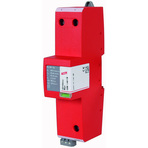
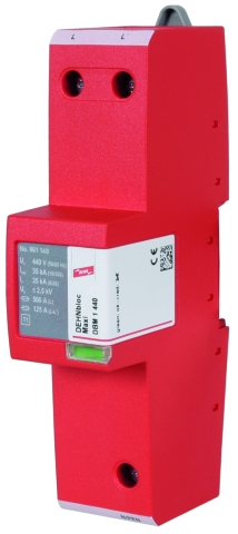
DEHNbloc® Maxi 440 / 760

Coordinated Lightning Current Arrester for Nominal Voltages of 400 V and 690 V

For protecting low-voltage consumer's installations against surges and even direct lightning strikes. For installation in conformity with the lightning protection zone concept at the boundaries from 0A– 1.
  • Spark-gap-based lightning current arrester
  • Extremely high lightning current discharge capacity
  • High follow current extinguishing capability and limitation due RADAX Flow technology
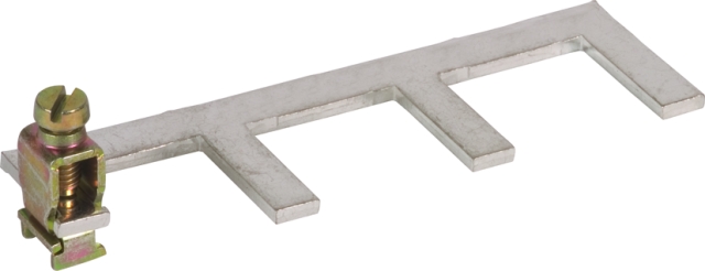
  • Directly coordinated with DEHNguard surge protective devices without additional cable length
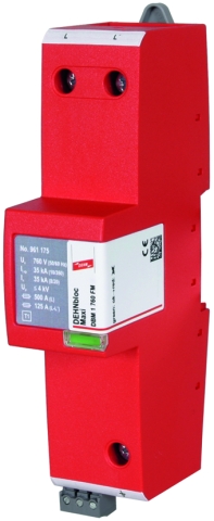
  • Operating state / fault indication by green / red indicator flag in the inspection window

Version

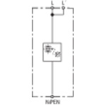
DEHNbloc Maxi 1 440: Coordinated single-pole lightning current arrester with high follow current limitation for UC = 440 V
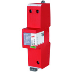
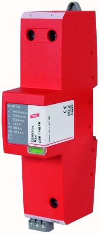
DEHNbloc Maxi 1 440 FM: With remote signalling contact for monitoring device (floating changeover contact)
DEHNbloc Maxi 1 760 FM: Coordinated single-pole lightning current arrester with high follow current limitation for UC = 760 V
With remote signalling contact for monitoring device (floating changeover contact)

Details

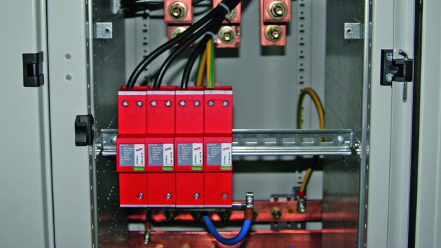
The coordinated DEHNbloc Maxi 440 and 760 lightning current arresters are specifically designed for high system voltages.
This allows to efficiently protect a variety of industrial applications from direct and indirect lightning currents.
Be it in a wind turbine or a stand-alone low-voltage installation of an industrial enterprise, DEHNbloc Maxi devices exactly fulfil the specific requirements.

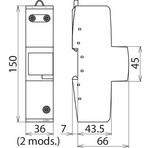
Both the design of the protective circuit and the enclosure specifically designed for this type of arrester are particularly adapted to high system voltages.
The approved RADAX Flow technology is the essential core element of the coordinated DEHNbloc Maxi 440 and 760 lightning current arresters. Their capability of considerably limiting mains follow currents and extinguishing them within a few milliseconds makes these devices special.
The patented RADAX Flow follow current limitation ensures that low-value fuses are not tripped by follow currents.
The capability to discharge lightning currents without destruction and to suppress mains follow currents without tripping upstream overcurrent protective devices ensures a high degree of availability in electrical installations.
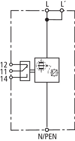
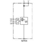
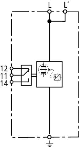
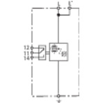
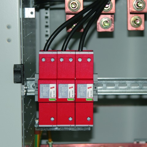
The operating state / fault indicator of the coordinated lightning current arresters needs no power to operate and immediately shows the operating state of the devices. Apart from the standard visual indication with green and red indicator flags, DEHNbloc Maxi 1 ... FM features a three-pole remote signalling terminal. With its floating changeover contact, the remote signal can be used as a break or make contact according to the particular circuit concept.

Models

DEHNbloc Maxi 1 440 (FM)

DEHNbloc Maxi 1 760 FM

DEHNbloc Maxi 1 440 (FM)

Basic circuit diagram DBM 1 440 FMDimension drawing DBM 1 440 FM

Coordinated single-pole lightning current arrester for use in 400 / 690 V systems; FM version with floating remote signalling contact.


Specifications

Type
Part No.
SPD according to EN 61643-11 / IEC 61643-11
Nominal voltage (a.c.) (UN)
Max. continuous operating voltage (a.c.) (UC)
Lightning impulse current (10/350 µs) (Iimp)
Specific energy (W/R)
Nominal discharge current (8/20 µs) (In)
Voltage protection level (UP)
Follow current extinguishing capability (a.c.) (Ifi)
Follow current limitation / Selectivity
Response time (tA)
Max. backup fuse (L) up to IK = 50 kArms (ta ≤ 0.2 s)
Max. backup fuse (L) up to IK = 50 kArms (ta ≤ 5 s)
Max. backup fuse (L-L')
Temporary overvoltage (TOV) (UT) – Characteristic
Operating temperature range (parallel connection) (TUP)
Operating temperature range (series connection) (TUS)
Operating state / fault indication
Number of ports
Cross-sectional area (L, L', N/PEN) (min.)
Cross-sectional area (L, N/PEN) (max.)
Cross-sectional area (L') (max.)
For mounting on
Enclosure material
Place of installation
Degree of protection
Capacity
Approvals
Type of remote signalling contact
Switching capacity (a.c.)
Switching capacity (d.c.)
Cross-sectional area for remote signalling terminals
Extended technical data:
– Max. prospective short-circuit current
– Limitation / Extinction of mains follow currents
– Max. backup fuse (L) up to IK = 100 kArms (ta ≤ 0.2 s)
– Max. backup fuse (L) up to IK = 100 kArms (ta ≤ 5 s)
Weight
GTIN
PU
Part No.
  • DBM 1 440
  • 961 140
  • type 1 / class I
  • 400 V
  • 440 V
  • 35 kA
  • 306.25 kJ/ohms
  • 35 kA
  • ≤ 2.5 kV
  • 50 kArms
  • no tripping of a 32 A gG fuse up to 50 kArms (prosp.)
  • ≤ 100 ns
  • 500 A gG
  • 250 A gG
  • 125 A gG
  • 760 V / 120 min. – withstand
  • -40 °C ... +80 °C
  • -40 °C ... +60 °C
  • green / red
  • 1
  • 10 mm2 solid / flexible
  • 50 mm2 stranded / 35 mm2 flexible
  • 35 mm2 stranded / 25 mm2 flexible
  • 35 mm DIN rails acc. to EN 60715
  • thermoplastic, red, UL 94 V-0
  • indoor installation
  • IP 20
  • 2 module(s), DIN 43880
  • UL, CSA
  •  
  •  
  •  
  •  
  • Use in switchgear installations with prospective short-circuit currents of more than 50 kArms (tested by the German VDE)
  • 100 kArms (220 kApeak)
  • up to 100 kArms (220 kApeak)
  • 500 A gG
  • 250 A gG
  • 516 g
  • 4013364116269
  • 1 pc(s)
  • 961 140
  • Specifications (PDF)
  • More
  • DBM 1 440 FM
  • 961 145
  • type 1 / class I
  • 400 V
  • 440 V
  • 35 kA
  • 306.25 kJ/ohms
  • 35 kA
  • ≤ 2.5 kV
  • 50 kArms
  • no tripping of a 32 A gG fuse up to 50 kArms (prosp.)
  • ≤ 100 ns
  • 500 A gG
  • 250 A gG
  • 125 A gG
  • 760 V / 120 min. – withstand
  • -40 °C ... +80 °C
  • -40 °C ... +60 °C
  • green / red
  • 1
  • 10 mm2 solid / flexible
  • 50 mm2 stranded / 35 mm2 flexible
  • 35 mm2 stranded / 25 mm2 flexible
  • 35 mm DIN rails acc. to EN 60715
  • thermoplastic, red, UL 94 V-0
  • indoor installation
  • IP 20
  • 2 module(s), DIN 43880
  • UL, CSA
  • changeover contact
  • 250 V / 0.5 A
  • 250 V / 0.1 A; 125 V / 0.2 A; 75 V / 0.5 A
  • max. 1.5 mm2 solid / flexible
  • Use in switchgear installations with prospective short-circuit currents of more than 50 kArms (tested by the German VDE)
  • 100 kArms (220 kApeak)
  • up to 100 kArms (220 kApeak)
  • 500 A gG
  • 250 A gG
  • 520 g
  • 4013364116276
  • 1 pc(s)
  • 961 145
  • Specifications (PDF)
  • More

DEHNbloc Maxi 1 760 FM

Basic circuit diagram DBM 1 760 FMDimension drawing DBM 1 760 FM

Coordinated single-pole lightning current arrester for use in 690 V systems; with remote signalling contact for monitoring device (floating changeover contact).


Specifications

Type
Part No.
SPD according to EN 61643-11 / IEC 61643-11
Nominal voltage (a.c.) (UN)
Max. continuous operating voltage (a.c.) (UC)
Lightning impulse current (10/350 µs) (Iimp)
Specific energy (W/R)
Nominal discharge current (8/20 µs) (In)
Voltage protection level (UP)
Follow current extinguishing capability (a.c.) (Ifi)
Follow current limitation / Selectivity
Response time (tA)
Max. backup fuse (L) up to IK = 25 kArms (ta ≤ 5 s)
Max. backup fuse (L) at IK > 25 kArms
Max. backup fuse (L-L')
Temporary overvoltage (TOV) (UT) – Characteristic
Operating temperature range (parallel connection) (TUP)
Operating temperature range (series connection) (TUS)
Operating state / fault indication
Number of ports
Cross-sectional area (L, L', 9) (min.)
Cross-sectional area (L, 9) (max.)
Cross-sectional area (L') (max.)
For mounting on
Enclosure material
Place of installation
Degree of protection
Capacity
Approvals
Type of remote signalling contact
Switching capacity (a.c.)
Switching capacity (d.c.)
Cross-sectional area for remote signalling terminals
Weight
GTIN
PU
Part No.
  • DBM 1 760 FM
  • 961 175
  • type 1 / class I
  • 690 V
  • 760 V
  • 25 kA
  • 156.25 kJ/ohms
  • 25 kA
  • ≤ 4 kV
  • 25 kArms
  • no tripping of a 32 A gG fuse up to 50 kArms (prosp.)
  • ≤ 100 ns
  • 250 A gG
  • 100 A gG
  • 125 A gG
  • 1320 V / 120 min. – withstand
  • -40 °C ... +80 °C
  • -40 °C ... +60 °C
  • green / red
  • 1
  • 10 mm2 solid / flexible
  • 50 mm2 stranded / 35 mm2 flexible
  • 35 mm2 stranded / 25 mm2 flexible
  • 35 mm DIN rails acc. to EN 60715
  • thermoplastic, red, UL 94 V-0
  • indoor installation
  • IP 20
  • 2 module(s), DIN 43880
  • UL, CSA
  • changeover contact
  • 250 V / 0.5 A
  • 250 V / 0.1 A; 125 V / 0.2 A; 75 V / 0.5 A
  • max. 1.5 mm2 solid / flexible
  • 507 g
  • 4013364116283
  • 1 pc(s)
  • 961 175
  • Specifications (PDF)
  • More

Accessories

Earthing Clip for two-module Enclosures, single-phase, three-pole

Earthing clip for connecting the earth terminal of e.g. three SPDs with two-module enclosure to earth, with terminal.

Show SpecificationsHide Specifications

Specifications

Type
Part No.
Dimensions
Terminal
Weight
GTIN
PU
  • EB DG 1000 1 3
  • 900 411
  • 34 x 112 x 28 mm
  • up to 25 mm2
  • 54 g
  • 4013364107205
  • 1 pc(s)
  • Specifications (PDF)
  • More
    • Further Pictures
      Further Information
      Product Specifications (Text)

      Back

      Three-pole EB DG 1000 1 3 earthing clip
      Earthing clip for connecting the earth terminal of e.g. three
      DEHNguard 1000 (FM) to earth, single-phase, three-pole
      Terminal up to 25 mm2
      Dimensions: (34 x 112 x 28) mm

      delivery and installation.

      Brand: DEHN
      Type: EB DG 1000 1 3
      Part No.: 900 411

      or equivalent.

Earthing Clip for two-module Enclosures, single-phase, four-pole

Earthing clip for connecting the earth terminal of e.g. four SPDs with two-module enclosure to earth, with terminal.

Show SpecificationsHide Specifications

Specifications

Type
Part No.
Dimensions
Terminal
Weight
GTIN
PU
  • EB 1 4 9
  • 900 417
  • 34 x 148 x 28 mm
  • up to 25 mm2
  • 66 g
  • 4013364120419
  • 1 pc(s)
  • Specifications (PDF)
  • More
    • Further Pictures
      Further Information
      Product Specifications (Text)

      Back

      Four-pole EB 1 4 9 earthing clip
      Earthing clip for connecting the earth terminal of e.g. 
      four DEHNbloc M 1 ... (FM) to earth, 
      single-phase, four-pole
      Terminal up to 25 mm2
      Dimensions: (34 x 148 x 28) mm

      delivery and installation.

      Brand: DEHN
      Type: EB 1 4 9
      Part No.: 900 417

      or equivalent.
      Certificates
      CE_EB_1_4_9