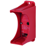
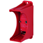
DEHNguard® PCB
Single-pole Base for DEHNguard Protection Modules
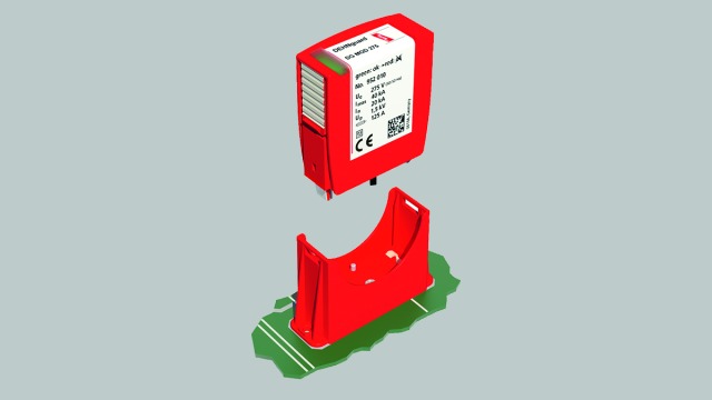
- Base for DEHNguard protection modules to be mounted on and integrated in PCBs
- Optimal integration of a type 2 arrester in devices
- Easy and flexible use for all circuit configurations
- Proven DEHNguard modules ensure high performance
- Coded base and protection module ensure against installing an incorrect module
- Version with and without remote signalling contact for the monitoring device
- Versions for maximum requirements on air clearances and creepage distances
- Versions for other DEHNguard protection modules available on request
Version
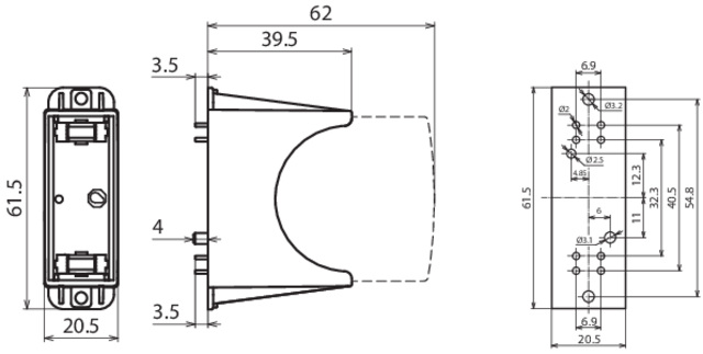
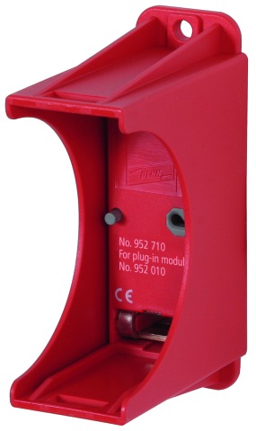
DEHNguard PCB ...: Base for mounting arresters on printed circuit boards
DEHNguard PCB ... FM: With remote signalling contact for monitoring device (floating changeover contact)
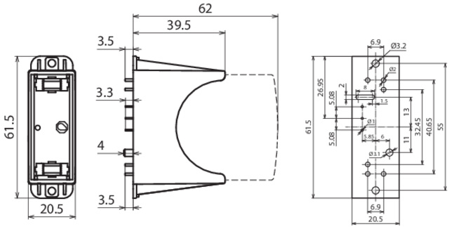
DEHNguard PCB … I … FM: With increased air clearances and creepage distances between the power and remote signalling contact
DEHNguard PCB ... FM: With remote signalling contact for monitoring device (floating changeover contact)
DEHNguard PCB … I … FM: With increased air clearances and creepage distances between the power and remote signalling contact
Details
The single-pole DEHNguard PCB ... (FM) base is specially designed for use on printed circuit boards (PCBs). Thus, surge protection can be taken into account at an early stage of development of the PCB and can be optimally integrated in the overall product. This single-pole version can be used for all system configurations. Fault-resistant Y circuits for PV systems or 3+1 configurations for a.c. systems can be easily implemented.
Thanks to the ideal positioning of the SPD on the device, an optimal voltage protection level is achieved for the electronics of the PCB since there is no cable length between the SPD and the device to be protected through which additional surges may be injected (in typical applications). The design of the PCB also allows series connection according to IEC 60364-5-53.
Various device features show that reliable surge protection and equipment reliability are a top priority of the modular DEHNguard. The application-oriented product designation, which makes it considerably easier to assign the protection modules to the relevant DG PCB base part, and the unique module locking system reflect the high safety requirements. The module locking system firmly fixes the protection modules to DEHNguard PCB (FM). Neither vibration in the application environment nor the dynamic forces of discharge can loosen the protection modules. Nevertheless, they can be easily replaced without tools by simply pressing the easy-to-use module release button of the protection modules.
Each DEHNguard PCB (FM) base and each protection module is mechanically coded to ensure against installing an incorrect module.
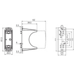
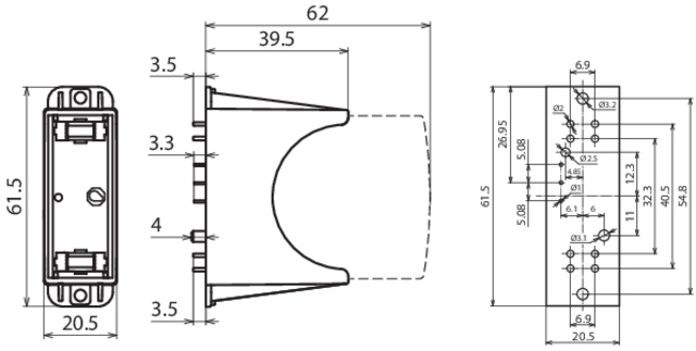
The DG PCB … I … FM versions ensure increased distances between the power and remote signalling contact since special applications place increased requirements on air clearances and creepage distances between these circuits. Details can be found in the drilling scheme of the installation instructions which can be downloaded free of charge at www.dehn-international.com.
The ...FM version of DG PCB... features a three-pole remote signalling contact. With its floating changeover contact, the remote signal can be used as a make or break contact according to the particular circuit concept.
Thanks to the ideal positioning of the SPD on the device, an optimal voltage protection level is achieved for the electronics of the PCB since there is no cable length between the SPD and the device to be protected through which additional surges may be injected (in typical applications). The design of the PCB also allows series connection according to IEC 60364-5-53.
Various device features show that reliable surge protection and equipment reliability are a top priority of the modular DEHNguard. The application-oriented product designation, which makes it considerably easier to assign the protection modules to the relevant DG PCB base part, and the unique module locking system reflect the high safety requirements. The module locking system firmly fixes the protection modules to DEHNguard PCB (FM). Neither vibration in the application environment nor the dynamic forces of discharge can loosen the protection modules. Nevertheless, they can be easily replaced without tools by simply pressing the easy-to-use module release button of the protection modules.
Each DEHNguard PCB (FM) base and each protection module is mechanically coded to ensure against installing an incorrect module.
The DG PCB … I … FM versions ensure increased distances between the power and remote signalling contact since special applications place increased requirements on air clearances and creepage distances between these circuits. Details can be found in the drilling scheme of the installation instructions which can be downloaded free of charge at www.dehn-international.com.
The ...FM version of DG PCB... features a three-pole remote signalling contact. With its floating changeover contact, the remote signal can be used as a make or break contact according to the particular circuit concept.