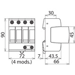
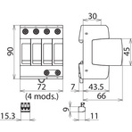
DEHNguard® modular with integrated Backup Fuse

Modular Surge Arrester with integrated Backup Fuse

For protecting low-voltage consumer's installations against surges. For installation in conformity with the lightning protection zone concept at the boundaries from 0B– 1 and higher.
  • Arrester backup fuse integrated in the protection module
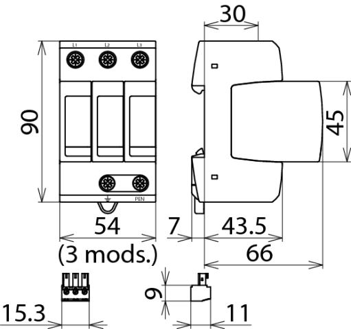
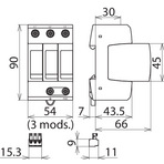
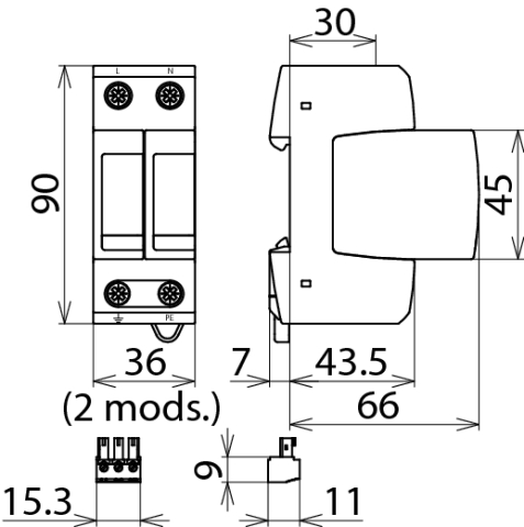
  • Prewired complete unit consisting of a base part and plug-in protection modules
  • Energy coordination with other arresters of the Red/Line product family
  • High discharge capacity
  • High reliability due to "Thermo Dynamic Control" SPD monitoring device
  • Easy replacement of protection modules without tools due to module locking system with module release button

Version

DEHNguard M TNC CI 275: Modular surge arrester with integrated backup fuse for TN-C systems
DEHNguard M TNS CI 275: With integrated backup fuse for TN-S systems
DEHNguard M TT CI 275: With integrated backup fuse for TT and TN-S systems (3+1 configuration)
DEHNguard M TN CI 275: With integrated backup fuse for 230 V TN systems
DEHNguard M TT 2P CI 275: With integrated backup fuse for 230 V TT and TN systems (1+1 configuration)
DEHNguard S CI 275: Modular single-pole surge arrester with integrated backup fuse
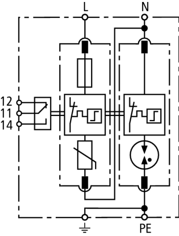
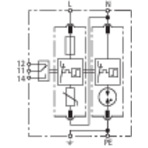
DEHNguard M ... CI 275 FM: With remote signalling contact for monitoring device (floating changeover contact)

Details

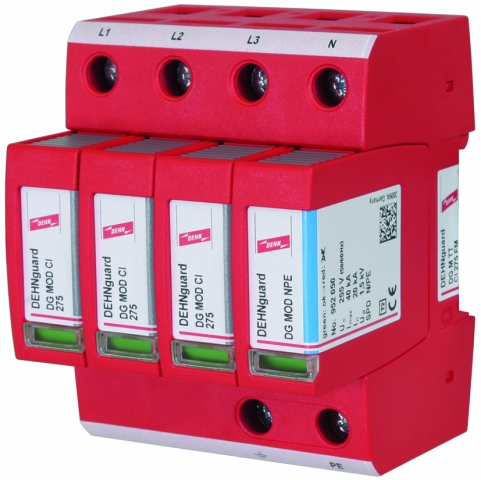
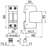
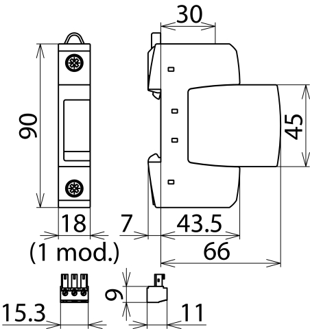
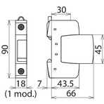
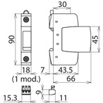
Featuring the functional Red/Line design, the modular surge arresters of the DEHNguard ... CI family combine short-circuit and surge protection in a single protection module with a width of only one module, setting new patterns for ease of application.
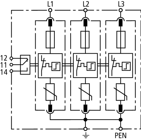
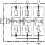
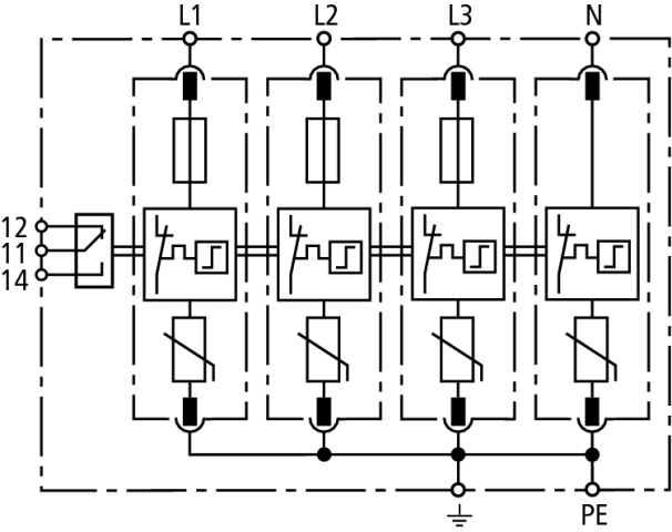
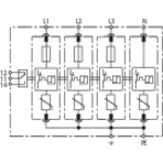
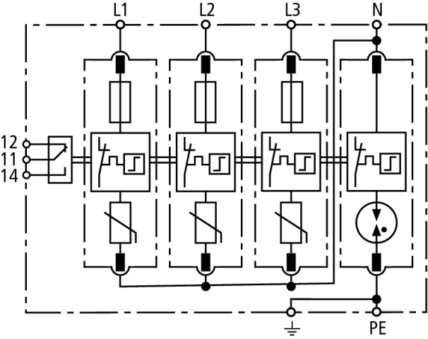
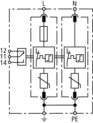
The protective circuit has the arrester backup fuse integrated in the protection module. This feature together with the heavy-duty zinc oxide varistor and the dual "Thermo Dynamic Control" monitoring device allow easy installation with minimum space requirements.
With the already integrated arrester backup fuse, the user no longer has to care about arrester-specific dimensioning requirements such as backup protection in the event of a short-circuit and impulse current carrying capability.
The integrated fuse has been developed especially for this case of application. It is not designed for permanent current but especially for impulse current and short-circuit protection thus, an optimal performance is ensured. The fuse never must be replaced separately because tripping of fuse is also end of SPD service life. Space-saving surge protection measures covering all functions specified in the installation standards can be implemented in installations with short-circuit currents up to 25 kArms. All paths including the N-PE path feature an operating state indicator as required by the IEC 60364-5-53 standard.
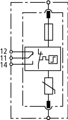
Due to the "Thermo Dynamic Control" monitoring device, the surface temperature of the heavy-duty varistor and the intensity of the discharge current are used for evaluation. The operating state of each protective path is shown by means of a mechanical indicator with green and red indicator flags which needs no power to operate. It also indicates the activation of the "Thermo Dynamic Control" monitoring device and the integrated arrester backup fuse.
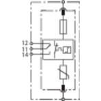
In addition to this mechanical operating state / fault indication, the ... FM version of the DEHNguard ... CI devices features a three-pole remote signalling terminal. With its floating changeover contact, the remote signal can be used as break or make contact according to the particular circuit concept.

All the benefits of the modular design of the DEHNguard family have been integrated into the new DEHNguard ... CI family.
The system-configuration-specific product designation and the "Thermo Dynamic Control" monitoring device reflect the high safety requirements.
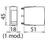
The unique module locking system prevents the protection modules from becoming loose due to vibration during transport or the enormous forces of discharge. Nevertheless, the protection modules can be easily replaced without tools, the need to de-energise and removing the distribution board cover by simply pressing the easy-to use module release button of the protection modules. Each protective circuit in the multipole and single-pole arresters and each protection module is mechanically coded to ensure against installing an incorrect protection module.

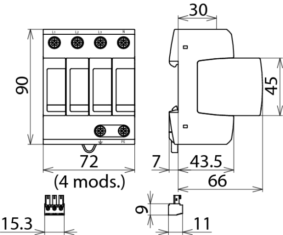
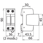
The surge arresters of the modular DEHNguard ... CI family feature multifunctional terminals on a standardised spacing of one module for connecting conductors and busbars, allowing easy wiring with other DIN rail mounted devices. Thus, a variety of applications can be easily connected in series in accordance with IEC 60364-5-53 for optimal protection.

Models

DEHNguard M TNC CI ... (FM)

DEHNguard M TNS CI ... (FM)

DEHNguard M TT CI ... (FM)

DEHNguard M TN CI ... (FM)

DEHNguard M TT 2P CI ... (FM)

DEHNguard S CI ... (FM)

DEHNguard M TNC CI ... (FM)

Basic circuit diagram DG M TNC CI ... FMDimension drawing DG M TNC CI ... FM

Modular surge arrester with integrated backup fuses for TN-C systems with a nominal voltage of 230 / 400 V (3+0 configuration); FM version with floating remote signalling contact.


Specifications

Type
Part No.
SPD according to EN 61643-11 / IEC 61643-11
Energy coordination with terminal equipment (≤ 10 m)
Nominal a.c. voltage (UN)
Max. continuous operating voltage (a.c.) (UC)
Nominal discharge current (8/20 µs) (In)
Max. discharge current (8/20 µs) (Imax)
Voltage protection level (UP)
Voltage protection level at 5 kA (UP)
Response time (tA)
Max. mains-side overcurrent protection
Rated breaking capacity of the internal backup protection
Short-circuit withstand capability (ISCCR)
Temporary overvoltage (TOV) (UT) – Characteristic
Operating temperature range (TU)
Operating state / fault indication
Number of ports
Cross-sectional area (min.)
Cross-sectional area (max.)
For mounting on
Enclosure material
Place of installation
Degree of protection
Capacity
Approvals
Type of remote signalling contact
Switching capacity (a.c.)
Switching capacity (d.c.)
Cross-sectional area for remote signalling terminals
Weight
GTIN
PU
Part No.
  • DG M TNC CI 275
  • 952 304
  • type 2 / class II
  • type 2 + type 3
  • 230 / 400 V (50 / 60 Hz)
  • 275 V (50 / 60 Hz)
  • 12.5 kA
  • 25 kA
  • ≤ 1.5 kV
  • ≤ 1 kV
  • ≤ 25 ns
  • not required
  • 25 kA
  • 25 kArms
  • 335 V / 5 sec. – withstand
  • 440 V / 120 min. – safe failure
  • -40 °C ... +80 °C
  • green / red
  • 1
  • 1.5 mm2 solid / flexible
  • 35 mm2 stranded / 25 mm2 flexible
  • 35 mm DIN rails acc. to EN 60715
  • thermoplastic, red, UL 94 V-0
  • indoor installation
  • IP 20
  • 3  module(s), DIN 43880
  • KEMA, VDE
  •  
  •  
  •  
  •  
  • 376 g
  • 4013364128361
  • 1 pc(s)
  • 952 304
  • Specifications (PDF)
  • More
  • DG M TNC CI 275 FM
  • 952 309
  • type 2 / class II
  • type 2 + type 3
  • 230 / 400 V (50 / 60 Hz)
  • 275 V (50 / 60 Hz)
  • 12.5 kA
  • 25 kA
  • ≤ 1.5 kV
  • ≤ 1 kV
  • ≤ 25 ns
  • not required
  • 25 kA
  • 25 kArms
  • 335 V / 5 sec. – withstand
  • 440 V / 120 min. – safe failure
  • -40 °C ... +80 °C
  • green / red
  • 1
  • 1.5 mm2 solid / flexible
  • 35 mm2 stranded / 25 mm2 flexible
  • 35 mm DIN rails acc. to EN 60715
  • thermoplastic, red, UL 94 V-0
  • indoor installation
  • IP 20
  • 3  module(s), DIN 43880
  • KEMA, VDE
  • changeover contact
  • 250 V / 0.5 A
  • 250 V / 0.1 A; 125 V / 0.2 A; 75 V / 0.5 A
  • max. 1.5 mm2 solid / flexible
  • 382 g
  • 4013364128378
  • 1 pc(s)
  • 952 309
  • Specifications (PDF)
  • More

DEHNguard M TNS CI ... (FM)

Basic circuit diagram DG M TNS CI ... FMDimension drawing DG M TNS CI ... FM

Modular surge arrester with integrated backup fuses for TN-S systems with a nominal voltage of 230 / 400 V (4+0 configuration); FM version with floating remote signalling contact.


Specifications

Type
Part No.
SPD according to EN 61643-11 / IEC 61643-11
Energy coordination with terminal equipment (≤ 10 m)
Nominal a.c. voltage (UN)
Max. continuous operating voltage (a.c.) (UC)
Nominal discharge current (8/20 µs) (In)
Max. discharge current (8/20 µs) (Imax)
Voltage protection level [L-PE] / [N-PE] (UP)
Voltage protection level [L-PE] / [N-PE] at 5 kA (UP)
Response time (tA)
Max. mains-side overcurrent protection
Rated breaking capacity of the internal backup protection
Short-circuit withstand capability (ISCCR)
Temporary overvoltage (TOV) (UT) – Characteristic
Operating temperature range (TU)
Operating state / fault indication
Number of ports
Cross-sectional area (min.)
Cross-sectional area (max.)
For mounting on
Enclosure material
Place of installation
Degree of protection
Capacity
Approvals
Type of remote signalling contact
Switching capacity (a.c.)
Switching capacity (d.c.)
Cross-sectional area for remote signalling terminals
Weight
GTIN
PU
Part No.
  • DG M TNS CI 275
  • 952 401
  • type 2 / class II
  • type 2 + type 3
  • 230 / 400 V (50 / 60 Hz)
  • 275 V (50 / 60 Hz)
  • 12.5 kA
  • 25 kA
  • ≤ 1.5 / ≤ 1.5 kV
  • ≤ 1 / ≤ 1 kV
  • ≤ 25 ns
  • not required
  • 25 kA
  • 25 kArms
  • 335 V / 5 sec. – withstand
  • 440 V / 120 min. – safe failure
  • -40 °C ... +80 °C
  • green / red
  • 1
  • 1.5 mm2 solid / flexible
  • 35 mm2 stranded / 25 mm2 flexible
  • 35 mm DIN rails acc. to EN 60715
  • thermoplastic, red, UL 94 V-0
  • indoor installation
  • IP 20
  • 4 module(s), DIN 43880
  • KEMA, VDE
  •  
  •  
  •  
  •  
  • 475 g
  • 4013364128347
  • 1 pc(s)
  • 952 401
  • Specifications (PDF)
  • More
  • DG M TNS CI 275 FM
  • 952 406
  • type 2 / class II
  • type 2 + type 3
  • 230 / 400 V (50 / 60 Hz)
  • 275 V (50 / 60 Hz)
  • 12.5 kA
  • 25 kA
  • ≤ 1.5 / ≤ 1.5 kV
  • ≤ 1 / ≤ 1 kV
  • ≤ 25 ns
  • not required
  • 25 kA
  • 25 kArms
  • 335 V / 5 sec. – withstand
  • 440 V / 120 min. – safe failure
  • -40 °C ... +80 °C
  • green / red
  • 1
  • 1.5 mm2 solid / flexible
  • 35 mm2 stranded / 25 mm2 flexible
  • 35 mm DIN rails acc. to EN 60715
  • thermoplastic, red, UL 94 V-0
  • indoor installation
  • IP 20
  • 4 module(s), DIN 43880
  • KEMA, VDE
  • changeover contact
  • 250 V / 0.5 A
  • 250 V / 0.1 A; 125 V / 0.2 A; 75 V / 0.5 A
  • max. 1.5 mm2 solid / flexible
  • 473 g
  • 4013364128354
  • 1 pc(s)
  • 952 406
  • Specifications (PDF)
  • More
    • Further Pictures
      Basic circuit diagram DG M TNS CI 275 FM
      open PDF
      Dimension drawing DG M TNS CI 275 FM
      open PDF
      Further Information
      Product Specifications (Text)

      Back

      DEHNguard M TNS CI 275 FM surge arrester with backup fuses
      Modular and pluggable four-pole surge arrester with integrated
      backup fuse for 230/400 V TN-S systems, width: 4 modules
      With remote signalling contact
      Type 2 SPD according to EN 61643-11
      Max. continuous operating voltage: 275 V a.c. 
      Voltage protection level: <= 1.5 kV
      Nominal discharge current: 12.5 kA
      Rated breaking capacity of the integrated backup protection: 25 kA
      Energy-coordinated according to IEC 62305-4 
      with arresters of the Red/Line series
      Mechanical fault indication for the arrester and integrated backup fuse 

      delivery and installation.

      Brand: DEHN
      Type: DG M TNS CI 275 FM
      Part No.: 952 406

      or equivalent.
      Installation Instructions
      Certificates
      2168398.01
      CE_DG_M_TNC_CI_275_FM
      40032221
      CAD-Data for registered Users
      952405.stp
      952405.igs
      952405.jt
      952405.dwg
      952405m_E.dxf

DEHNguard M TT CI ... (FM)

Basic circuit diagram DG M TT CI ... FMDimension drawing DG M TT CI ... FM

Modular surge arrester with integrated backup fuses for TT and TN-S systems with a nominal voltage of 230 / 400 V (3+1 configuration); FM version with floating remote signalling contact.


Specifications

Type
Part No.
SPD according to EN 61643-11 / IEC 61643-11
Energy coordination with terminal equipment (≤ 10 m)
Nominal a.c. voltage (UN)
Max. continuous operating voltage (a.c.) [L-N] (UC)
Max. continuous operating voltage (a.c.) [N-PE] (UC)
Nominal discharge current (8/20 µs) [L-N] (In)
Nominal discharge current (8/20 µs) [N-PE] (In)
Max. discharge current (8/20 µs) [L-N] (Imax)
Max. discharge current (8/20 µs) [N-PE] (Imax)
Lightning impulse current (10/350 µs) [N-PE] (Iimp)
Voltage protection level [L-N] / [N-PE] (UP)
Voltage protection level [L-N] / [N-PE] at 5 kA (UP)
Follow current extinguishing capability [N-PE] (Ifi)
Response time [L-N] (tA)
Response time [N-PE] (tA)
Max. mains-side overcurrent protection
Rated breaking capacity of the internal backup protection
Short-circuit withstand capability (ISCCR)
Temporary overvoltage (TOV) [L-N] (UT) – Characteristic
Temporary overvoltage (TOV) [N-PE] (UT) – Characteristic
Operating temperature range (TU)
Operating state / fault indication
Number of ports
Cross-sectional area (min.)
Cross-sectional area (max.)
For mounting on
Enclosure material
Place of installation
Degree of protection
Capacity
Approvals
Type of remote signalling contact
Switching capacity (a.c.)
Switching capacity (d.c.)
Cross-sectional area for remote signalling terminals
Extended technical data:
Voltage protection level [L-PE] (UP)
Weight
GTIN
PU
Part No.
  • DG M TT CI 275
  • 952 322
  • type 2 / class II
  • type 2 + type 3
  • 230 / 400 V (50 / 60 Hz)
  • 275 V (50 / 60 Hz)
  • 255 V (50 / 60 Hz)
  • 12.5 kA
  • 20 kA
  • 25 kA
  • 40 kA
  • 12 kA
  • ≤ 1.5 / ≤ 1.5 kV
  • ≤ 1 / ≤ 1.5 kV
  • 100 Arms
  • ≤ 25 ns
  • ≤ 100 ns
  • not required
  • 25 kA
  • 25 kArms
  • 335 V / 5 sec. – withstand
  • 440 V / 120 min. – safe failure
  • 1200 V / 200 ms – withstand
  • -40 °C ... +80 °C
  • green / red
  • 1
  • 1.5 mm2 solid / flexible
  • 35 mm2 stranded / 25 mm2 flexible
  • 35 mm DIN rails acc. to EN 60715
  • thermoplastic, red, UL 94 V-0
  • indoor installation
  • IP 20
  • 4 module(s), DIN 43880
  • KEMA, VDE
  •  
  •  
  •  
  •  
  • ---------------------------------
  • 1.5 kV
  • 456 g
  • 4013364128385
  • 1 pc(s)
  • 952 322
  • Specifications (PDF)
  • More
    • Further Pictures
      Basic circuit diagram DG M TT CI 275
      open PDF
      Dimension drawing DG M TT CI 275
      open PDF
      Further Information
      Product Specifications (Text)

      Back

      DEHNguard M TT CI 275 surge arrester with backup fuses
      Modular and pluggable four-pole surge arrester with integrated
      backup fuse for 230/400 V TT and TN-S systems, width: 4 modules
      Type 2 SPD according to EN 61643-11
      Max. continuous operating voltage: 275 V a.c. 
      Voltage protection level: <= 1.5 kV
      Nominal discharge current: 12.5 kA
      Rated breaking capacity of the integrated backup protection: 25 kA
      Energy-coordinated according to IEC 62305-4 
      with arresters of the Red/Line series
      Mechanical fault indication for the arrester and integrated backup fuse 

      delivery and installation.

      Brand: DEHN
      Type: DG M TT CI 275
      Part No.: 952 322

      or equivalent.
      Installation Instructions
      Certificates
      CE_DG_M_TT_CI_275_FM
      40032221
      2168398.01
      CAD-Data for registered Users
      952400.stp
      952400.igs
      952400.jt
      952400.dwg
      952400m_E.dxf
  • DG M TT CI 275 FM
  • 952 327
  • type 2 / class II
  • type 2 + type 3
  • 230 / 400 V (50 / 60 Hz)
  • 275 V (50 / 60 Hz)
  • 255 V (50 / 60 Hz)
  • 12.5 kA
  • 20 kA
  • 25 kA
  • 40 kA
  • 12 kA
  • ≤ 1.5 / ≤ 1.5 kV
  • ≤ 1 / ≤ 1.5 kV
  • 100 Arms
  • ≤ 25 ns
  • ≤ 100 ns
  • not required
  • 25 kA
  • 25 kArms
  • 335 V / 5 sec. – withstand
  • 440 V / 120 min. – safe failure
  • 1200 V / 200 ms – withstand
  • -40 °C ... +80 °C
  • green / red
  • 1
  • 1.5 mm2 solid / flexible
  • 35 mm2 stranded / 25 mm2 flexible
  • 35 mm DIN rails acc. to EN 60715
  • thermoplastic, red, UL 94 V-0
  • indoor installation
  • IP 20
  • 4  module(s), DIN 43880
  • KEMA, VDE
  • changeover contact
  • 250 V / 0.5 A
  • 250 V / 0.1 A; 125 V / 0.2 A; 75 V / 0.5 A
  • max. 1.5 mm2 solid / flexible
  • ---------------------------------
  • 1.5 kV
  • 475 g
  • 4013364128392
  • 1 pc(s)
  • 952 327
  • Specifications (PDF)
  • More
    • Further Pictures
      Basic circuit diagram  DG M TT CI 275 FM
      open PDF
      Dimension drawing  DG M TT CI 275 FM
      open PDF
      Further Information
      Product Specifications (Text)

      Back

      DEHNguard M TT CI 275 FM surge arrester with backup fuses
      Modular and pluggable four-pole surge arrester with integrated
      backup fuse for 230/400 V TT and TN-S systems, width: 4 modules
      With remote signalling contact
      Type 2 SPD according to EN 61643-11
      Max. continuous operating voltage: 275 V a.c. 
      Voltage protection level: <= 1.5 kV
      Nominal discharge current: 12.5 kA
      Rated breaking capacity of the integrated backup protection: 25 kA
      Energy-coordinated according to IEC 62305-4 
      with arresters of the Red/Line series
      Mechanical fault indication for the arrester and integrated backup fuse 

      delivery and installation.

      Brand: DEHN
      Type: DG M TT CI 275 FM
      Part No.: 952 327

      or equivalent.
      Installation Instructions
      Certificates
      CE_DG_M_TT_CI_275_FM
      40032221
      2168398.01
      CAD-Data for registered Users
      952405.stp
      952405.igs
      952405.jt
      952405.dwg
      952405m_E.dxf

DEHNguard M TN CI ... (FM)

Basic circuit diagram DG M TN CI ... FMDimension drawing DG M TN CI ... FM

Modular surge arrester with integrated backup fuses for single-phase 230 V TN systems (2+0 configuration); FM version with floating remote signalling contact.


Specifications

Type
Part No.
SPD according to EN 61643-11 / IEC 61643-11
Energy coordination with terminal equipment (≤ 10 m)
Nominal a.c. voltage (UN)
Max. continuous operating voltage (a.c.) (UC)
Nominal discharge current (8/20 µs) (In)
Max. discharge current (8/20 µs) (Imax)
Voltage protection level [L-PE] / [N-PE] (UP)
Voltage protection level [L-PE] / [N-PE] at 5 kA (UP)
Response time (tA)
Max. mains-side overcurrent protection
Rated breaking capacity of the internal backup protection
Short-circuit withstand capability (ISCCR)
Temporary overvoltage (TOV) (UT) – Characteristic
Operating temperature range (TU)
Operating state / fault indication
Number of ports
Cross-sectional area (min.)
Cross-sectional area (max.)
For mounting on
Enclosure material
Place of installation
Degree of protection
Capacity
Approvals
Type of remote signalling contact
Switching capacity (a.c.)
Switching capacity (d.c.)
Cross-sectional area for remote signalling terminals
Weight
GTIN
PU
Part No.
  • DG M TN CI 275
  • 952 173
  • type 2 / class II
  • type 2 + type 3
  • 230 V (50 / 60 Hz)
  • 275 V (50 / 60 Hz)
  • 12.5 kA
  • 25 kA
  • ≤ 1.5 / ≤ 1.5 kV
  • ≤ 1 / ≤ 1 kV
  • ≤ 25 ns
  • not required
  • 25 kA
  • 25 kArms
  • 335 V / 5 sec. – withstand
  • 440 V / 120 min. – safe failure
  • -40 °C ... +80 °C
  • green / red
  • 1
  • 1.5 mm2 solid / flexible
  • 35 mm2 stranded / 25 mm2 flexible
  • 35 mm DIN rails acc. to EN 60715
  • thermoplastic, red, UL 94 V-0
  • indoor installation
  • IP 20
  • 2 module(s), DIN 43880
  • KEMA, VDE
  •  
  •  
  •  
  •  
  • 257 g
  • 4013364128408
  • 1 pc(s)
  • 952 173
  • Specifications (PDF)
  • More
  • DG M TN CI 275 FM
  • 952 178
  • type 2 / class II
  • type 2 + type 3
  • 230 V (50 / 60 Hz)
  • 275 V (50 / 60 Hz)
  • 12.5 kA
  • 25 kA
  • ≤ 1.5 / ≤ 1.5 kV
  • ≤ 1 / ≤ 1 kV
  • ≤ 25 ns
  • not required
  • 25 kA
  • 25 kArms
  • 335 V / 5 sec. – withstand
  • 440 V / 120 min. – safe failure
  • -40 °C ... +80 °C
  • green / red
  • 1
  • 1.5 mm2 solid / flexible
  • 35 mm2 stranded / 25 mm2 flexible
  • 35 mm DIN rails acc. to EN 60715
  • thermoplastic, red, UL 94 V-0
  • indoor installation
  • IP 20
  • 2 module(s), DIN 43880
  • KEMA, VDE
  • changeover contact
  • 250 V / 0.5 A
  • 250 V / 0.1 A; 125 V / 0.2 A; 75 V / 0.5 A
  • max. 1.5 mm2 solid / flexible
  • 264 g
  • 4013364128415
  • 1 pc(s)
  • 952 178
  • Specifications (PDF)
  • More
    • Further Pictures
      Basic circuit diagram  DG M TN CI 275 FM
      open PDF
      Dimension drawing  DG M TN CI 275 FM
      open PDF
      Further Information
      Product Specifications (Text)

      Back

      DEHNguard M TN CI 275 FM surge arrester with backup fuses
      Modular and pluggable two-pole surge arrester with integrated
      backup fuse for single-phase 230 V TN systems, width: 2 modules
      Type 2 SPD according to EN 61643-11
      Max. continuous operating voltage: 275 V a.c. 
      Voltage protection level: <= 1.5 kV
      Nominal discharge current: 12.5 kA
      Rated breaking capacity of the integrated backup protection: 25 kA
      Energy-coordinated according to IEC 62305-4 
      with arresters of the Red/Line series
      Mechanical fault indication for the arrester and integrated backup fuse

      delivery and installation.

      Brand: DEHN
      Type: DG M TN CI 275 FM
      Part No.: 952 178

      or equivalent.
      Installation Instructions
      Certificates
      40032221
      CE_DG_M_TN_CI_275_FM
      2168398.01
      CAD-Data for registered Users
      952205.stp
      952205.igs
      952205.jt
      952205.dwg
      952205m_E.dxf

DEHNguard M TT 2P CI ... (FM)

Basic circuit diagram DG M TT 2P CI ... FMDimension drawing DG M TT 2P CI ... FM

Modular surge arrester with integrated backup fuses for single-phase 230 V TT and TN systems (1+1 configuration); FM version with floating remote signalling contact.


Specifications

Type
Part No.
SPD according to EN 61643-11 / IEC 61643-11
Energy coordination with terminal equipment (≤ 10 m)
Nominal a.c. voltage (UN)
Max. continuous operating voltage (a.c.) [L-N] (UC)
Max. continuous operating voltage (a.c.) [N-PE] (UC)
Nominal discharge current (8/20 µs) [L-N] (In)
Nominal discharge current (8/20 µs) [N-PE] (In)
Max. discharge current (8/20 µs) [L-N] (Imax)
Max. discharge current (8/20 µs) [N-PE] (Imax)
Lightning impulse current (10/350 µs) [N-PE] (Iimp)
Voltage protection level [L-N] / [N-PE] (UP)
Voltage protection level [L-N] / [N-PE] at 5 kA (UP)
Follow current extinguishing capability [N-PE] (Ifi)
Response time [L-N] (tA)
Response time [N-PE] (tA)
Max. mains-side overcurrent protection
Rated breaking capacity of the internal backup protection
Short-circuit withstand capability (ISCCR)
Temporary overvoltage (TOV) [L-N] (UT) – Characteristic
Temporary overvoltage (TOV) [N-PE] (UT) – Characteristic
Operating temperature range (TU)
Operating state / fault indication
Number of ports
Cross-sectional area (min.)
Cross-sectional area (max.)
For mounting on
Enclosure material
Place of installation
Degree of protection
Capacity
Approvals
Type of remote signalling contact
Switching capacity (a.c.)
Switching capacity (d.c.)
Cross-sectional area for remote signalling terminals
Extended technical data:
Voltage protection level [L-PE] (UP)
Weight
GTIN
PU
Part No.
  • DG M TT 2P CI 275
  • 952 171
  • type 2 / class II
  • type 2 + type 3
  • 230 V (50 / 60 Hz)
  • 275 V (50 / 60 Hz)
  • 255 V (50 / 60 Hz)
  • 12.5 kA
  • 20 kA
  • 25 kA
  • 40 kA
  • 12 kA
  • ≤ 1.5 / ≤ 1.5 kV
  • ≤ 1 / ≤ 1.5 kV
  • 100 Arms
  • ≤ 25 ns
  • ≤ 100 ns
  • not required
  • 25 kA
  • 25 kArms
  • 335 V / 5 sec. – withstand
  • 440 V / 120 min. – safe failure
  • 1200 V / 200 ms – withstand
  • -40 °C ... +80 °C
  • green / red
  • 1
  • 1.5 mm2 solid / flexible
  • 35 mm2 stranded / 25 mm2 flexible
  • 35 mm DIN rails acc. to EN 60715
  • thermoplastic, red, UL 94 V-0
  • indoor installation
  • IP 20
  • 2 module(s), DIN 43880
  • KEMA, VDE
  •  
  •  
  •  
  •  
  • ---------------------------------
  • 1.5 kV
  • 233 g
  • 4013364128422
  • 1 pc(s)
  • 952 171
  • Specifications (PDF)
  • More
  • DG M TT 2P CI 275 FM
  • 952 176
  • type 2 / class II
  • type 2 + type 3
  • 230 V (50 / 60 Hz)
  • 275 V (50 / 60 Hz)
  • 255 V (50 / 60 Hz)
  • 12.5 kA
  • 20 kA
  • 25 kA
  • 40 kA
  • 12 kA
  • ≤ 1.5 / ≤ 1.5 kV
  • ≤ 1 / ≤ 1.5 kV
  • 100 Arms
  • ≤ 25 ns
  • ≤ 100 ns
  • not required
  • 25 kA
  • 25 kArms
  • 335 V / 5 sec. – withstand
  • 440 V / 120 min. – safe failure
  • 1200 V / 200 ms – withstand
  • -40 °C ... +80 °C
  • green / red
  • 1
  • 1.5 mm2 solid / flexible
  • 35 mm2 stranded / 25 mm2 flexible
  • 35 mm DIN rails acc. to EN 60715
  • thermoplastic, red, UL 94 V-0
  • indoor installation
  • IP 20
  • 2 module(s), DIN 43880
  • KEMA, VDE
  • changeover contact
  • 250 V / 0.5 A
  • 250 V / 0.1 A; 125 V / 0.2 A; 75 V / 0.5 A
  • max. 1.5 mm2 solid / flexible
  • ---------------------------------
  • 1.5 kV
  • 260 g
  • 4013364128439
  • 1 pc(s)
  • 952 176
  • Specifications (PDF)
  • More

DEHNguard S CI ... (FM)

Basic circuit diagram DG S CI ... FMDimension drawing DG S CI ... FM

Pluggable single-pole surge arrester consisting of a base part and plug-in protection module; with integrated backup fuse; FM version with floating remote signalling contact.


Specifications

Type
Part No.
SPD according to EN 61643-11 / IEC 61643-11
Energy coordination with terminal equipment (≤ 10 m)
Nominal a.c. voltage (UN)
Max. continuous operating voltage (a.c.) (UC)
Nominal discharge current (8/20 µs) (In)
Max. discharge current (8/20 µs) (Imax)
Voltage protection level (UP)
Voltage protection level at 5 kA (UP)
Response time (tA)
Max. mains-side overcurrent protection
Rated breaking capacity of the internal backup protection
Short-circuit withstand capability (ISCCR)
Temporary overvoltage (TOV) (UT) – Characteristic
Operating temperature range (TU)
Operating state / fault indication
Number of ports
Cross-sectional area (min.)
Cross-sectional area (max.)
For mounting on
Enclosure material
Place of installation
Degree of protection
Capacity
Approvals
Type of remote signalling contact
Switching capacity (a.c.)
Switching capacity (d.c.)
Cross-sectional area for remote signalling terminals
Weight
GTIN
PU
Part No.
  • DG S CI 275
  • 952 079
  • type 2 / class II
  • type 2 + type 3
  • 230 V (50 / 60 Hz)
  • 275 V (50 / 60 Hz)
  • 12.5 kA
  • 25 kA
  • ≤ 1.5 kV
  • ≤ 1 kV
  • ≤ 25 ns
  • not required
  • 25 kA
  • 25 kArms
  • 335 V / 5 sec. – withstand
  • 440 V / 120 min. – safe failure
  • -40 °C ... +80 °C
  • green / red
  • 1
  • 1.5 mm2 solid / flexible
  • 35 mm2 stranded / 25 mm2 flexible
  • 35 mm DIN rails acc. to EN 60715
  • thermoplastic, red, UL 94 V-0
  • indoor installation
  • IP 20
  • 1 module(s), DIN 43880
  • KEMA, VDE
  •  
  •  
  •  
  •  
  • 141 g
  • 4013364128446
  • 1 pc(s)
  • 952 079
  • Specifications (PDF)
  • More
    • Further Pictures
      Basic circuit diagram
      open PDF
      Dimension drawing DG S CI 275
      open PDF
      Further Information
      Product Specifications (Text)

      Back

      DEHNguard S CI 275 surge arrester with backup fuses
      Modular and pluggable single-pole surge arrester with integrated
      backup fuse, width: 1 module
      Type 2 SPD according to EN 61643-11
      Max. continuous operating voltage: 275 V a.c./350 V d.c.
      Voltage protection level: <= 1.5 kV
      Nominal discharge current: 12.5 kA
      No additional backup fuse required in installations with a max. short-circuit current up to 25 kArms
      Energy-coordinated according to IEC 62305-4 
      with arresters of the Red/Line series
      Mechanical fault indication for the arrester and integrated backup fuse 

      delivery and installation.

      Brand: DEHN
      Type: DG S CI 275
      Part No.: 952 079

      or equivalent.
      Installation Instructions
      Certificates
      40032221
      CE_DG_S_CI_275_FM
      2168398.01
      CAD-Data for registered Users
      952070.stp
      952070.igs
      952070.jt
      952070.dwg
      952070m_E.dxf
  • DG S CI 275 FM
  • 952 099
  • type 2 / class II
  • type 2 + type 3
  • 230 V (50 / 60 Hz)
  • 275 V (50 / 60 Hz)
  • 12.5 kA
  • 25 kA
  • ≤ 1.5 kV
  • ≤ 1 kV
  • ≤ 25 ns
  • not required
  • 25 kA
  • 25 kArms
  • 335 V / 5 sec. – withstand
  • 440 V / 120 min. – safe failure
  • -40 °C ... +80 °C
  • green / red
  • 1
  • 1.5 mm2 solid / flexible
  • 35 mm2 stranded / 25 mm2 flexible
  • 35 mm DIN rails acc. to EN 60715
  • thermoplastic, red, UL 94 V-0
  • indoor installation
  • IP 20
  • 1 module(s), DIN 43880
  • KEMA, VDE
  • changeover contact
  • 250 V / 0.5 A
  • 250 V / 0.1 A; 125 V / 0.2 A; 75 V / 0.5 A
  • max. 1.5 mm2 solid / flexible
  • 129 g
  • 4013364128453
  • 1 pc(s)
  • 952 099
  • Specifications (PDF)
  • More
    • Further Pictures
      Basic circuit diagram DG S CI 275 FM
      open PDF
      Dimension drawing DG S CI 275 FM
      open PDF
      Further Information
      Product Specifications (Text)

      Back

       DEHNguard S CI 275 FM surge arrester with backup fuses
      Modular and pluggable single-pole surge arrester with integrated
      backup fuse, width: 1 module
      With remote signalling contact
      Type 2 SPD according to EN 61643-11
      Max. continuous operating voltage: 275 V a.c./350 V d.c.
      Voltage protection level: <= 1.5 kV
      Nominal discharge current: 12.5 kA
      No additional backup fuse required in installations with a max. short-circuit current up to 25 kArms
      Energy-coordinated according to IEC 62305-4 
      with arresters of the Red/Line series
      Mechanical fault indication for the arrester and integrated backup fuse 

      delivery and installation.

      Brand: DEHN
      Type: DG S CI 275 FM
      Part No.: 952 099

      or equivalent.
      Installation Instructions
      Certificates
      2168398.01
      40032221
      CE_DG_S_CI_275_FM
      CAD-Data for registered Users
      952090.stp
      952090.igs
      952090.jt
      952090.dwg
      952090m_E.dxf

Accessories

DEHNpanel

Visual remote indicator for (multiple) surge protective devices (SPDs)

Show SpecificationsHide Specifications

Specifications

Type
Part No.
Operating state/fault indication
Enclosure material
Weight
GTIN
PU
  • DPAN L
  • 910 200
  • green LED (flashing) / red LED (flashing)
  • noryl
  • 140 g
  • 4013364144019
  • 1 pc(s)
  • Specifications (PDF)
  • More
    • Further Pictures
      open PDF
      Further Information
      Product Specifications (Text)

      Back

      DPAN L visual remote indication for surge protective devices
      Visual remote indicator with current-saving LEDs for surge protective devices (SPDs) 
      With remote signalling contact
      Also suited for alarm signalling of other devices with floating changeover contact
      For installation in switchgear cabinet doors.
      Power supply: 2x 1.5 V AA batteries
      Degree of protection: IP 40
      Mounting dimensions: 92 x 45 mm
      Dimensions: 96 x 48 x 75 mm

      delivery and installation.

      Brand: DEHN
      Type: DPAN L
      Part No.: 910 200

      or equivalent.
      Installation Instructions
      Certificates
      CE_DEHNpanel

Varistor-Based Protection Module for DEHNguard M CI

Protection module for DEHNguard M ... CI 275 surge arresters comprising a varistor connected in series with the integrated backup fuse.

Show SpecificationsHide Specifications

Specifications

Type
Part No.
Max. continuous operating voltage (a.c.) (UC)
Weight
GTIN
PU

Varistor-Based Protection Module

Varistor-based protection module for DEHNguard M ... and DEHNguard S ... surge arresters.

Show SpecificationsHide Specifications

Specifications

Type
Part No.
Max. continuous operating voltage (a.c.) (UC)
Weight
GTIN
PU

N-PE Spark-Gap-Based Protection Module for DEHNguard M TT ...

N-PE spark-gap-based protection module for two-pole and four-pole DEHNguard DG M TT ... surge arresters.

Show SpecificationsHide Specifications

Specifications

Type
Part No.
Max. continuous operating voltage (a.c.) (UC)
Weight
GTIN
PU

STAK 25 Pin-shaped Terminal

Allows series connection (connection of two conductors) of surge protective devices up to 25 mm2.
Allows EMC-optimised feed-through wiring according to IEC 60364-5-53.

Show SpecificationsHide Specifications

Specifications

Type
Part No.
Nominal a.c./d.c. voltage (UN)
Nominal load current a.c. (IL)
Lightning impulse current (10/350 µs)
Weight
GTIN
PU

STAK 3X16 Pin-shaped Terminal

Pin-shaped terminal for EMC-optimised series connection of lightning current and surge arresters according to IEC 60364-5-53.

Show SpecificationsHide Specifications

Specifications

Type
Part No.
Weight
GTIN
PU