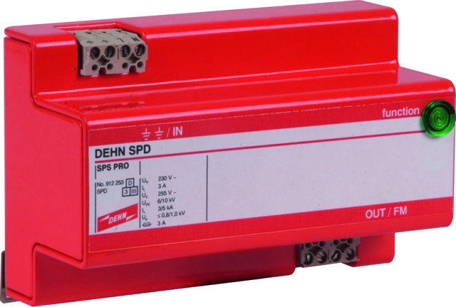
SPS Protector

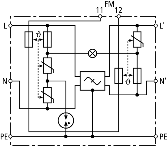
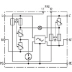
Two-pole surge arrester with filter

For protecting the power supply circuits of industrial electronics equipment (e.g. programmable logic controls (PLCs)) against transients and high-frequency interference voltages. For installation in conformity with the lightning protection zone concept at the boundaries from 1 – 2 and higher.
  • Combination of surge protection and filter
  • Surge protection with monitoring device and disconnector
  • Interference suppressor filter for protecting sensitive industrial electronics equipment against balanced and unbalanced high-frequency interference
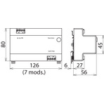
  • Integrated in a shielded enclosure
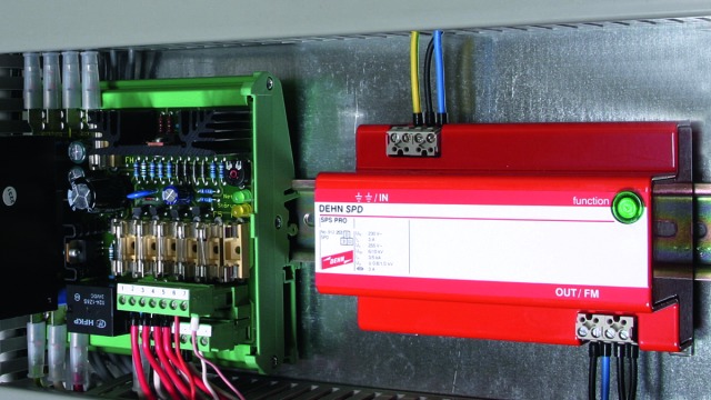
  • Visual operating state indication (green) and floating remote signalling contact (break contact) for fault indication

Version

SPS Protector: Two-pole surge arrester with interference suppressor filter

Details

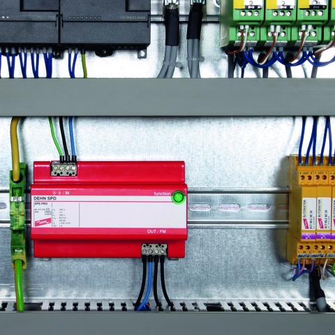
The SPS Protector combines surge protection and interference suppressor filter in a compact device. This makes it ideal for protecting sensitive terminal equipment of industrial automation systems (e.g. programmable logic controls (PLCs)). The coordinated surge protection and filter functions complement one another and prevent core saturation of the filter in the event of high-level transients. The separate input and output terminals provide optimal protection for the device to be protected. The metal enclosure of the SPS Protector ensures that high-frequency interferences are discharged without interfering with other devices in the immediate vicinity. The compact design of the SPS Protector already houses the proven disconnector. In case of overload, it disconnects the arrester without interrupting the power supply circuit. Apart from the green indicator light, SPS Protectors also feature a remote signalling contact.

Models

SPS Protector

SPS Protector

Basic circuit diagram SPS PRODimension drawing SPS PRO

Surge arrester with interference suppressor filter for single-phase 230 V TT and TN systems; with floating remote signalling contact.


Specifications

Type
Part No.
SPD according to EN 61643-11 / IEC 61643-11
Nominal voltage (a.c.) (UN)
Max. continuous operating voltage (a.c.) (UC)
Nominal load current (a.c.) (IL)
Voltage drop in percent [L'-N'/L-N] for UC/IL (∆U)
Nominal discharge current (8/20 µs) (In)
Combination wave (UOC)
Total discharge current (8/20 µs) [L+N-PE] (Itotal)
Voltage protection level [L-N] / [L/N-PE] (UP)
Combination wave [L+N-PE] (UOC total)
Response time [L-N] (tA)
Response time [L/N-PE] (tA)
Short-circuit withstand capability for max. mains-side overcurrent protection (ISCCR)
Temporary overvoltage (TOV) [L-N] (UT) – Characteristic
Temporary overvoltage (TOV) [L/N] (UT) – Characteristic
Temporary overvoltage (TOV) [L/N-PE] (UT) – Characteristic
Temporary overvoltage (TOV) [L+N-PE] (UT) – Characteristic
Operating state indication
Fault indication
Number of ports
Operating temperature range (TU)
Cross-sectional area (min.)
Cross-sectional area (max.)
For mounting on
Enclosure material
Place of installation
Degree of protection
Capacity
Type of remote signalling contact
Switching capacity (a.c.)
Switching capacity (d.c.)
Cross-sectional area for remote signalling terminals
Mains filter
Attenuation for f = 1 MHz, balanced
Attenuation for f = 1 MHz, unbalanced
Weight
GTIN
PU
Part No.
  • SPS PRO
  • 912 253
  • type 3 / class III
  • 230 V (50 / 60 Hz)
  • 255 V (50 / 60 Hz)
  • 3 A
  • ≤ 1.6 %
  • 3 kA
  • 6 kV
  • 5 kA
  • ≤ 800 / ≤ 1000 V
  • 10 kV
  • ≤ 25 ns
  • ≤ 100 ns
  • 1 kArms
  • 335 V / 5 sec. – withstand
  • 440 V / 120 min. – safe failure
  • 335 V / 120 min. – withstand
  • 440 V / 5 sec. – withstand
  • 1200 V + UREF / 200 ms – safe failure
  • green light
  • green light off
  • 2
  • -10 °C ... +40 °C
  • 0.14 mm2 solid / stranded / flexible
  • 2.5 mm2 solid / stranded / flexible
  • 35 mm DIN rails acc. to EN 60715
  • aluminium, red powder coating
  • indoor installation
  • IP 20
  • 7 modules, DIN 43880
  • break contact
  • 250 V / 0.5 A
  • 250 V / 0.1 A; 125 V / 0.2 A; 75 V / 0.5 A
  • max. 1.5 mm2 solid / flexible
  • acc. to DIN VDE 0565-3
  • ≥ 73 dB
  • ≥ 45 dB
  • 563 g
  • 4013364068360
  • 1 pc(s)
  • 912 253
  • Specifications (PDF)
  • More
    • Further Pictures
      Basic circuit diagram SPS PRO
      open PDF
      Dimension drawing SPS PRO
      open PDF
      Further Information
      Product Specifications (Text)

      Back

      Two-pole SPS PRO surge arrester with interference suppressor filter 
      Two-pole surge arrester for protecting
      the power supply circuit of electronic devices
      against transient overvoltage and 
      high-frequency interference 
      Width: 7 mod.
      Type 3 SPD according to EN 61643-11
      Operating state indication: 	green
      Fault indication: remote signalling contact
      In a shielded enclosure
      Mains filter according to DIN VDE 0565 Part 3
      Max. continuous operating voltage: 255 V a.c.
      Total discharge current: 5 kA
      Voltage protection level (L-N): <= 0.8 kV 
      Nominal load current: 3 A a.c.
      Attenuation at f = 1 MHz balanced/unbalanced >= 73 dB / >= 45 dB
      Energy-coordinated according to IEC 62305-4 with arresters 
      of the Red/Line series

      delivery and installation.

      Brand: DEHN
      Type: SPS PRO
      Part No.: 912 253

      or equivalent.
      Installation Instructions
      Certificates
      CE_SPS_PRO
      CAD-Data for registered Users
      912253.stp
      912253.igs
      912253.jt
      912253.dwg
      912253m_E.dxf