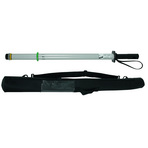
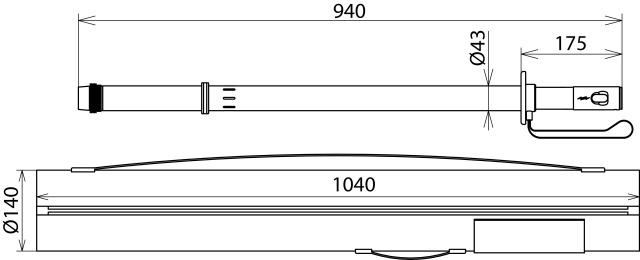
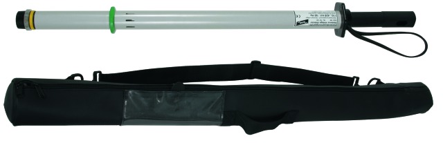
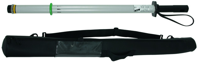
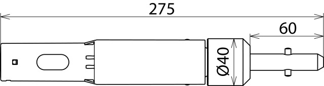
HSA 194 High-Voltage Indicator
Nominal Voltage Range 110 ... 420 kV / 16.7 and 50 Hz
- Easy and safe testing
- For contactlessly verifying that switchgear and high-voltage overhead lines or centre-earthed monophase traction power lines are dead
- Cost-effective / space-saving transport
Bild 1
Special instructions for the use of HSA 194 110 420 SN7737 (Part No. 767539)
The device can be switched between the "climbing check" mode (switch position when climbing the tower) and the "110 ... 420 kV" mode for verifying that the overhead conductor is dead.
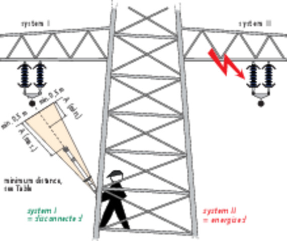
Switch position “climbing check”
When climbing the lattice tower, the switch position “climbing check” allows to check from the corner leg whether the next overhead conductor (or conductor bundle) is still energised when approaching it. During this check, the high-voltage indicator is moved closer towards the next overhead conductor and moved within 0.5 m (see Fig. 1). If the conductor is energised, there is a visual (red flashing light) and acoustic signal.
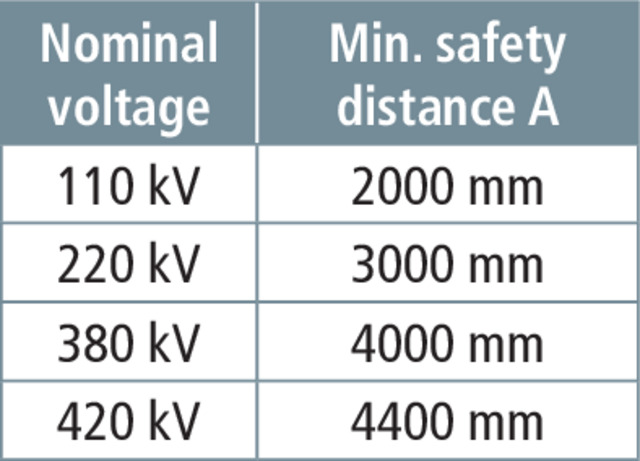
The minimum distance A (min) (according to the nominal voltage in Table 2) between the operating head of the high-voltage indicator and the overhead conductor must be observed.
The customer must determine the maximum distance A (max) (safe tripping of the high-voltage indicator when approaching the overhead conductor) depending on the nominal voltage and document it in the operating instructions.
Using the high-voltage indicator when climbing lattice towers does not replace verifying absence of voltage from the cross arm.
The device can be switched between the "climbing check" mode (switch position when climbing the tower) and the "110 ... 420 kV" mode for verifying that the overhead conductor is dead.
Switch position “climbing check”
When climbing the lattice tower, the switch position “climbing check” allows to check from the corner leg whether the next overhead conductor (or conductor bundle) is still energised when approaching it. During this check, the high-voltage indicator is moved closer towards the next overhead conductor and moved within 0.5 m (see Fig. 1). If the conductor is energised, there is a visual (red flashing light) and acoustic signal.
The minimum distance A (min) (according to the nominal voltage in Table 2) between the operating head of the high-voltage indicator and the overhead conductor must be observed.
The customer must determine the maximum distance A (max) (safe tripping of the high-voltage indicator when approaching the overhead conductor) depending on the nominal voltage and document it in the operating instructions.
Using the high-voltage indicator when climbing lattice towers does not replace verifying absence of voltage from the cross arm.
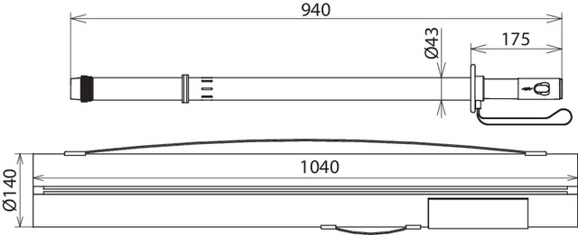
Bild 2
General application notes for the HSA 194
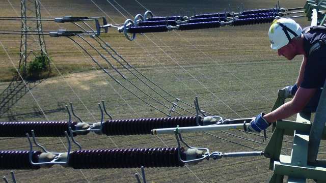
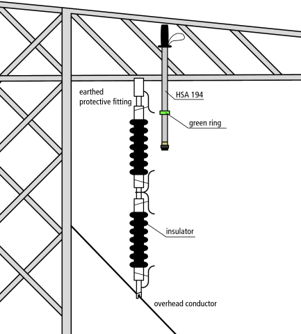
Switch position voltage range "110 … 420 kV“
To verify absence of voltage from the tower cross arm, place the green ring of the high-voltage indicator on the last earthed protective fitting (or earthed insulator cap) of the insulator so that the operating head of the high-voltage indicator (see Fig. 2) points towards the overhead conductor to be tested, which is attached to the other insulator end (longitudinal axis of the device in parallel to the longitudinal axis of the insulator). If the conductor is energised, there is a visual (red flashing light) and acoustic signal.