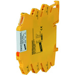
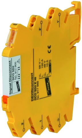
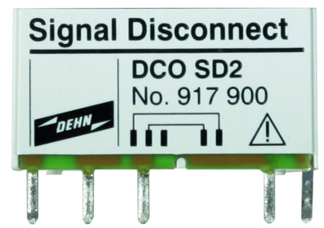
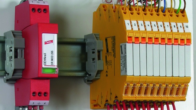
DEHNconnect SD2

Terminal Block with integrated Surge Protection

Application example: DEHNconnect for protecting the I/O of PLC interfaces.
    Terminal block with integrated surge protection
  • For protecting measuring and control circuits and bus systems
  • Maximum impulse current carrying capability Imax up to 20 kA (8/20 µs)
  • Low voltage protection level, capable of protecting terminal equipment
  • No back up fuse up to 500 mA
  • Modular disconnection function
  • Disconnection module for disconnecting the signal circuit for maintenance work
  • Module fixing and mechanical ejector
  • Module in "parked" position after disconnection
  • Space-saving and function-optimised design
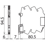
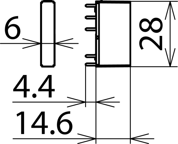
  • Terminal block with integrated surge protection (width of 6 mm)
  • Fast conductor connection without tools thanks to direct plug-in technology
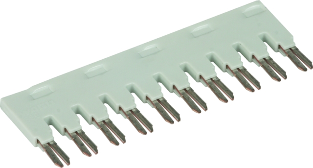
  • Can be used with jumper bar (accessory)

Description

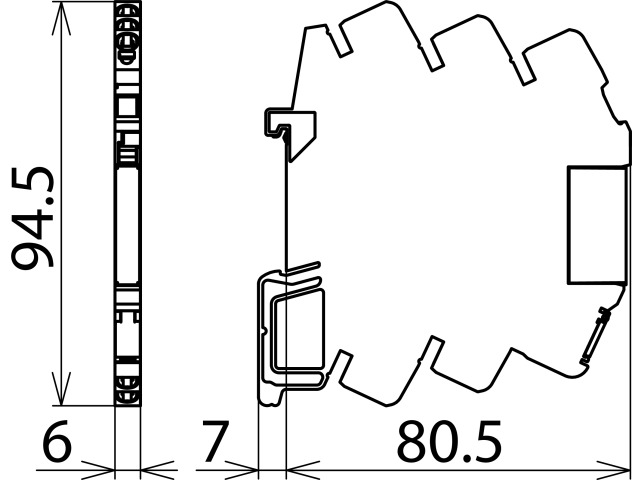
The surge arresters of the DEHNconnect SD2 series are designed as space-saving terminal blocks with a width of 6 mm. These terminal blocks with integrated surge protection have a modular disconnection function that allows them to interrupt the signal circuit for maintenance work. An integrated module ejector disconnects the signal circuit from the terminal equipment. The disconnection module does not have to be removed, but remains in a "parked" position in the module slot.
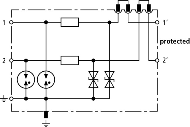
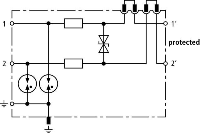
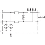
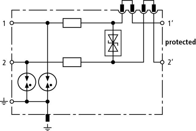
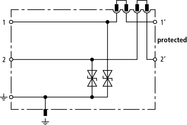
Different types of arresters are available and protect two single lines sharing a common reference potential (unbalanced interfaces) or an unearthed pair (balanced interface). Arresters with a high cut-off frequency (HF) can be used for balanced bus interfaces with high data rates (e.g. Profibus, RS485).

Conductors are connected via a vibration-proof spring-loaded connection system. Stripped solid conductors and flexible conductors with wire end ferrule can be easily and quickly inserted into the relevant conductor terminal without the use of tools. For rewiring, the conductor is removed from the clamping point and clamped into a new conductor terminal.

To reduce wiring, jumper bars can be inserted at the protected side of the surge arrester, thus quickly connecting signal circuits.

The arresters are ideally suited for use in industrial environments at information technology signal interfaces of automation, measuring and control as well as bus systems.

Detail 1

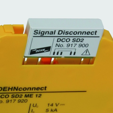
Disconnection module with ejector – for disconnecting the signal circuits.

Detail 2

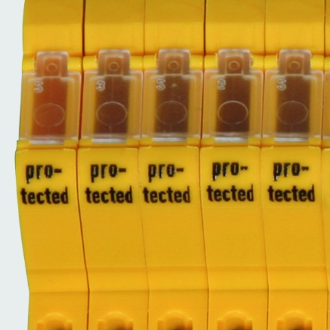
Marking of the protected side – minimises wiring errors.

Detail 3

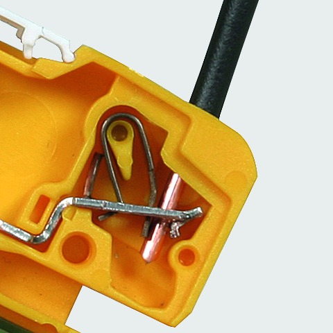
Terminals with direct-plug-in technology – fast and vibration-proof connection.

Detail 4

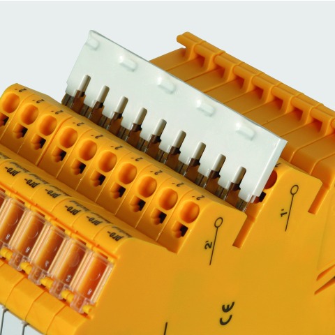
Slots for jumper bars – for quickly connecting signal circuits.

Models

DCO SD2 ME

DCO SD2 MD

DCO SD2 MD HF

DCO SD2 E

DCO SD2 ME

Basic circuit diagram DCO SD2 MEDimension drawing DCO SD2 ME

Energy-coordinated surge arrester with disconnection function for protecting two single lines sharing a common reference potential as well as unbalanced interfaces.


Specifications

Type
Part No.
SPD class
Nominal voltage (UN)
Max. continuous operating voltage (d.c.) (UC)
Max. continuous operating voltage (a.c.) (UC)
Nominal current at 80 °C (IL)
D1 Lightning impulse current (10/350 µs) per line (Iimp)
C2 Total nominal discharge current (8/20 µs) (In)
C2 Nominal discharge current (8/20 µs) per line (In)
Voltage protection level line-line for In C2 (Up)
Voltage protection level line-PG for In C2 (Up)
Voltage protection level line-line at 1 kV/µs C3 (Up)
Voltage protection level line-PG at 1 kV/µs C3 (UP)
Series resistance per line
Cut-off frequency line-PG (fG)
Capacitance line-line (C)
Capacitance line-PG (C)
Operating temperature range (TU)
Degree of protection
For mounting on
Connection (input / output)
Cross-sectional area (solid)
Cross-sectional area (flexible)
Earthing via
Enclosure material
Colour
Test standards
Approvals
SIL classification
ATEX approvals
IECEx approvals
Extended technical data:
– Max. discharge current (8/20 µs) [1/2 - PG], [1+2 - PG] (Imax)
– Voltage protection level line-PG at 1 kV/μs C3 after being subjected to Imax (Up)
Weight
GTIN
PU
Part No.
*) For more detailed information, please visit www.dehn-international.com.
  • DCO SD2 ME 12
  • 917 920
  • Q
  • 12 V
  • 14 V
  • 9.5 V
  • 0.5 A
  • 1 kA
  • 10 kA
  • 5 kA
  • ≤ 60 V
  • ≤ 50 V
  • ≤ 36 V
  • ≤ 19 V
  • 1.8 ohms
  • 2.5 MHz
  • ≤ 1.2 nF
  • ≤ 2.4 nF
  • -40 °C ... +80 °C
  • IP 00
  • 35 mm DIN rails acc. to EN 60715
  • spring / spring
  • 0.34-2.5 mm2
  • 0.34-2.5 mm2
  • DIN rail / terminal
  • polyamide PA 6.6
  • yellow
  • IEC 61643-21 / EN 61643-21
  • UL, CSA, SIL, EAC, ATEX, IECEx
  • up to SIL3 *)
  • DEKRA 17ATEX0046 X: II 3 G Ex ec IIC T6...T4 Gc
  • DEK 17.0023X: Ex ec IIC T6...T4 Gc
  • - - - - - - - - - - - - - - - - - - - -
  • 20 kA
  • ≤ 19 V
  • 32 g
  • 4013364150560
  • 1 pc(s)
  • 917 920
  • Specifications (PDF)
  • More
  • DCO SD2 ME 24
  • 917 921
  • Q
  • 24 V
  • 33 V
  • 23 V
  • 0.5 A
  • 1 kA
  • 10 kA
  • 5 kA
  • ≤ 120 V
  • ≤ 75 V
  • ≤ 90 V
  • ≤ 45 V
  • 1.8 ohms
  • 6 MHz
  • ≤ 0.5 nF
  • ≤ 1.0 nF
  • -40 °C ... +80 °C
  • IP 00
  • 35 mm DIN rails acc. to EN 60715
  • spring / spring
  • 0.34-2.5 mm2
  • 0.34-2.5 mm2
  • DIN rail / terminal
  • polyamide PA 6.6
  • yellow
  • IEC 61643-21 / EN 61643-21
  • UL, CSA, SIL, EAC, ATEX, IECEx
  • up to SIL3 *)
  • DEKRA 17ATEX0046 X: II 3 G Ex ec IIC T6...T4 Gc
  • DEK 17.0023X: Ex ec IIC T6...T4 Gc
  • - - - - - - - - - - - - - - - - - - - -
  • 20 kA
  • ≤ 45 V
  • 31 g
  • 4013364150577
  • 1 pc(s)
  • 917 921
  • Specifications (PDF)
  • More
  • DCO SD2 ME 48
  • 917 922
  • Q
  • 48 V
  • 55 V
  • 38.5 V
  • 0.5 A
  • 1 kA
  • 10 kA
  • 5 kA
  • ≤ 180 V
  • ≤ 110 V
  • ≤ 150 V
  • ≤ 75 V
  • 1.8 ohms
  • 7.5 MHz
  • ≤ 0.3 nF
  • ≤ 0.6 nF
  • -40 °C ... +80 °C
  • IP 00
  • 35 mm DIN rails acc. to EN 60715
  • spring / spring
  • 0.34-2.5 mm2
  • 0.34-2.5 mm2
  • DIN rail / terminal
  • polyamide PA 6.6
  • yellow
  • IEC 61643-21 / EN 61643-21
  • UL, CSA, SIL, EAC, ATEX, IECEx
  • up to SIL3 *)
  • DEKRA 17ATEX0046 X: II 3 G Ex ec IIC T6...T4 Gc
  • DEK 17.0023X: Ex ec IIC T6...T4 Gc
  • - - - - - - - - - - - - - - - - - - - -
  • 20 kA
  • ≤ 75 V
  • 31 g
  • 4013364150584
  • 1 pc(s)
  • 917 922
  • Specifications (PDF)
  • More

DCO SD2 MD

Basic circuit diagram DCO SD2 MDDimension drawing DCO SD2 MD

Energy-coordinated surge arrester with disconnection function for protecting one unearthed pair as well as balanced interfaces.


Specifications

Type
Part No.
SPD class
Nominal voltage (UN)
Max. continuous operating voltage (d.c.) (UC)
Max. continuous operating voltage (a.c.) (UC)
Nominal current at 80 °C (IL)
D1 Lightning impulse current (10/350 µs) per line (Iimp)
C2 Total nominal discharge current (8/20 µs) (In)
C2 Nominal discharge current (8/20 µs) per line (In)
Voltage protection level line-line for In C2 (Up)
Voltage protection level line-PG for In C2 (Up)
Voltage protection level line-line at 1 kV/µs C3 (Up)
Voltage protection level line-PG at 1 kV/µs C3 (UP)
Series resistance per line
Cut-off frequency line-PG (fG)
Capacitance line-line (C)
Capacitance line-PG (C)
Operating temperature range (TU)
Degree of protection
For mounting on
Connection (input / output)
Cross-sectional area (solid)
Cross-sectional area (flexible)
Earthing via
Enclosure material
Colour
Test standards
Approvals
SIL classification
ATEX approvals
IECEx approvals
Extended technical data:
– Max. discharge current (8/20 µs) [1/2 - PG], [1+2 - PG] (Imax)
– Voltage protection level line-PG at 1 kV/μs C3 after being subjected to Imax (Up)
Weight
GTIN
PU
Part No.
*) For more detailed information, please visit www.dehn-international.com.
  • DCO SD2 MD 12
  • 917 940
  • Q
  • 12 V
  • 14 V
  • 9.5 V
  • 0.5 A
  • 1 kA
  • 10 kA
  • 5 kA
  • ≤ 30 V
  • ≤ 750 V
  • ≤ 19 V
  • ≤ 650 V
  • 1.8 ohms
  • 2.5 MHz
  • ≤ 2.4 nF
  • ≤ 6 pF
  • -40 °C ... +80 °C
  • IP 00
  • 35 mm DIN rails acc. to EN 60715
  • spring / spring
  • 0.34-2.5 mm2
  • 0.34-2.5 mm2
  • DIN rail / terminal
  • polyamide PA 6.6
  • yellow
  • IEC 61643-21 / EN 61643-21
  • UL, CSA, SIL, EAC, ATEX, IECEx
  • up to SIL3 *)
  • DEKRA 17ATEX0046 X: II 3 G Ex ec IIC T6...T4 Gc
  • DEK 17.0023X: Ex ec IIC T6...T4 Gc
  • - - - - - - - - - - - - - - - - - - - -
  • 20 kA
  • ≤ 650 V
  • 31 g
  • 4013364150591
  • 1 pc(s)
  • 917 940
  • Specifications (PDF)
  • More
  • DCO SD2 MD 24
  • 917 941
  • Q
  • 24 V
  • 33 V
  • 23 V
  • 0.5 A
  • 1 kA
  • 10 kA
  • 5 kA
  • ≤ 50 V
  • ≤ 750 V
  • ≤ 45 V
  • ≤ 650 V
  • 1.8 ohms
  • 6 MHz
  • ≤ 1.0 nF
  • ≤ 6 pF
  • -40 °C ... +80 °C
  • IP 00
  • 35 mm DIN rails acc. to EN 60715
  • spring / spring
  • 0.34-2.5 mm2
  • 0.34-2.5 mm2
  • DIN rail / terminal
  • polyamide PA 6.6
  • yellow
  • IEC 61643-21 / EN 61643-21
  • UL, CSA, SIL, EAC, ATEX, IECEx
  • up to SIL3 *)
  • DEKRA 17ATEX0046 X: II 3 G Ex ec IIC T6...T4 Gc
  • DEK 17.0023X: Ex ec IIC T6...T4 Gc
  • - - - - - - - - - - - - - - - - - - - -
  • 20 kA
  • ≤ 650 V
  • 31 g
  • 4013364150607
  • 1 pc(s)
  • 917 941
  • Specifications (PDF)
  • More
  • DCO SD2 MD 48
  • 917 942
  • Q
  • 48 V
  • 55 V
  • 38.5 V
  • 0.5 A
  • 1 kA
  • 10 kA
  • 5 kA
  • ≤ 100 V
  • ≤ 750 V
  • ≤ 72 V
  • ≤ 650 V
  • 1.8 ohms
  • 8 MHz
  • ≤ 0.6 nF
  • ≤ 6 pF
  • -40 °C ... +80 °C
  • IP 00
  • 35 mm DIN rails acc. to EN 60715
  • spring / spring
  • 0.34-2.5 mm2
  • 0.34-2.5 mm2
  • DIN rail / terminal
  • polyamide PA 6.6
  • yellow
  • IEC 61643-21 / EN 61643-21
  • UL, CSA, SIL, EAC, ATEX, IECEx
  • up to SIL3 *)
  • DEKRA 17ATEX0046 X: II 3 G Ex ec IIC T6...T4 Gc
  • DEK 17.0023X: Ex ec IIC T6...T4 Gc
  • - - - - - - - - - - - - - - - - - - - -
  • 20 kA
  • ≤ 650 V
  • 31 g
  • 4013364150614
  • 1 pc(s)
  • 917 942
  • Specifications (PDF)
  • More

DCO SD2 MD HF

Basic circuit diagram DCO SD2 MD HFDimension drawing DCO SD2 MD HF

Energy-coordinated surge arrester with disconnection function for protecting balanced interfaces with extra-low voltages. Also suitable for high transmission rates due to a diode matrix with minimised capacitance. It is advisable to use SAK shield connection systems for shielded bus lines.


Specifications

Type
Part No.
SPD class
Nominal voltage (UN)
Max. continuous operating voltage (d.c.) (UC)
Max. continuous operating voltage (a.c.) (UC)
Nominal current at 80 °C (IL)
D1 Lightning impulse current (10/350 µs) per line (Iimp)
C2 Total nominal discharge current (8/20 µs) (In)
C2 Nominal discharge current (8/20 µs) per line (In)
Voltage protection level line-line for In C2 (Up)
Voltage protection level line-PG for In C2 (Up)
Voltage protection level line-line at 1 kV/µs C3 (Up)
Voltage protection level line-PG at 1 kV/µs C3 (UP)
Series resistance per line
Cut-off frequency line-line (fG)
Capacitance line-line (C)
Capacitance line-PG (C)
Operating temperature range (TU)
Degree of protection
For mounting on
Connection (input / output)
Cross-sectional area (solid)
Cross-sectional area (flexible)
Earthing via
Enclosure material
Colour
Test standards
Approvals
SIL classification
ATEX approvals
IECEx approvals
Extended technical data:
– Max. discharge current (8/20 µs) [1/2 - PG], [1+2 - PG] (Imax)
– Voltage protection level line-PG at 1 kV/μs C3 after being subjected to Imax (Up)
Weight
GTIN
PU
Part No.
*) For more detailed information, please visit www.dehn-international.com.
  • DCO SD2 MD HF 5
  • 917 970
  • Q
  • 5 V
  • 8.5 V
  • 6.0 V
  • 0.5 A
  • 1 kA
  • 10 kA
  • 5 kA
  • ≤ 35 V
  • ≤ 750 V
  • ≤ 14 V
  • ≤ 650 V
  • 1.8 ohm
  • 100 MHz
  • ≤ 25 pF
  • ≤ 10 pF
  • -40 °C ... +80 °C
  • IP 00
  • 35 mm DIN rails acc. to EN 60715
  • spring / spring
  • 0.34-2.5 mm2
  • 0.34-2.5 mm2
  • DIN rail / terminal
  • polyamide PA 6.6
  • yellow
  • IEC 61643-21 / EN 61643-21
  • UL, CSA, SIL, EAC, ATEX, IECEx
  • up to SIL3 *)
  • DEKRA 17ATEX0046 X: II 3 G Ex ec IIC T6...T4 Gc
  • DEK 17.0023X: Ex ec IIC T6...T4 Gc
  • - - - - - - - - - - - - - - - - - - - -
  • 20 kA
  • ≤ 650 V
  • 31 g
  • 4013364150621
  • 1 pc(s)
  • 917 970
  • Specifications (PDF)
  • More

DCO SD2 E

Basic circuit diagram DCO SD2 EDimension drawing DCO SD2 E

Finely-limiting surge protective device with disconnection function for two single lines sharing a common reference potential and unbalanced interfaces.


Specifications

Type
Part No.
SPD class
Nominal voltage (UN)
Max. continuous operating voltage (d.c.) (UC)
Max. continuous operating voltage (a.c.) (UC)
Nominal current at 60 °C (IL)
C1 Total nominal discharge current (8/20 µs) (In)
C1 Nominal discharge current (8/20 µs) per line (In)
Voltage protection level line-line for In C1 (Up)
Voltage protection level line-PG for In C1 (Up)
Voltage protection level line-line at 1 kV/µs C3 (Up)
Voltage protection level line-PG at 1 kV/µs C3 (UP)
Cut-off frequency line-PG (fG)
Capacitance line-line (C)
Capacitance line-PG (C)
Operating temperature range (TU)
Degree of protection
For mounting on
Connection (input / output)
Cross-sectional area (solid)
Cross-sectional area (flexible)
Earthing via
Enclosure material
Colour
Test standards
Approvals
SIL classification
Weight
GTIN
PU
Part No.
*) For more detailed information, please visit www.dehn-international.com.

Accessories

Signal Disconnect Disconnection Module

Disconnection module (replacement) to be inserted in DCO SD2 for disconnecting the signal in the system circuit.

Show SpecificationsHide Specifications

Specifications

Type
Part No.
Width
Weight
GTIN
PU
  • DCO SD2
  • 917 900
  • 6 mm
  • 3 g
  • 4013364150676
  • 5 pc(s)
  • Specifications (PDF)
  • More
    • Further Pictures
      open PDF
      Further Information
      Product Specifications (Text)

      Back

      DCO SD2 disconnection module for signal 
      disconnection in the system circuit
      Plug-in module for insertion
      into terminal blocks with
      integrated surge protection of 
      the DEHNconnect DCO SD2 
      series for signal disconnection in
      the system circuit

      delivery and installation.

      Brand: DEHN
      Type: DCO SD2
      Part No.: 917 900

      or equivalent.
      Installation Instructions

Jumper Bar

Multipole jumper bar for DCO SD2 terminal blocks with integrated surge protection.

Show SpecificationsHide Specifications

Specifications

Type
Part No.
Poles
Weight
GTIN
PU
  • KB 10 DCO RK
  • 919 880
  • 10
  • 5 g
  • 4013364095090
  • 25 pc(s)
  • Specifications (PDF)
  • More
    • Further Pictures
      Further Information
      Product Specifications (Text)

      Back

      KB 10 DCO RK jumper bar
      Jumper bar for DEHNconnect RK, 10 poles

      delivery and installation.

      Brand: DEHN
      Type: KB 10 DCO RK
      Part No.: 919 880

      or equivalent.

Quick Labelling System, horizontal Imprint

Plate with 2x plate numbers from 1 to 50 for DCO SD2, horizontal imprint

Show SpecificationsHide Specifications

Specifications

Type
Part No.
Material
Weight
GTIN
PU
  • LS 1 50 H DCO
  • 917 977
  • plastic
  • 9 g
  • 4013364151536
  • 1 pc(s)
  • Specifications (PDF)
  • More
    • Further Pictures
      Further Information
      Product Specifications (Text)

      Back

      LS 1 50 H DCO quick labelling system, horizontal imprint
      Quick labelling system for DEHNconnect SD2,
      horizontally printed 

      delivery and installation.

      Brand: DEHN
      Type: LS 1 50 H DCO
      Part No.: 917 977

      or equivalent.