Voltage-controlled smart decoupling device VCSD
Smart decoupling device VCSD

- VCSD: Voltage Controlled Smart Decoupling Device
- Protection in case of transient, temporary and long-duration overvoltages
- Does not negatively affect cathodic protection equipment
- Adjustable response threshold for flexible use in a wide range of application and operating states
Version
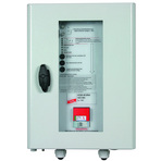
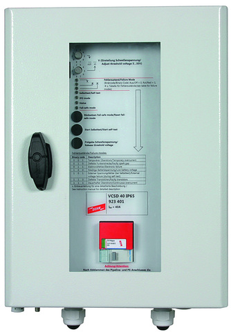
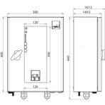
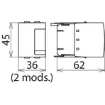
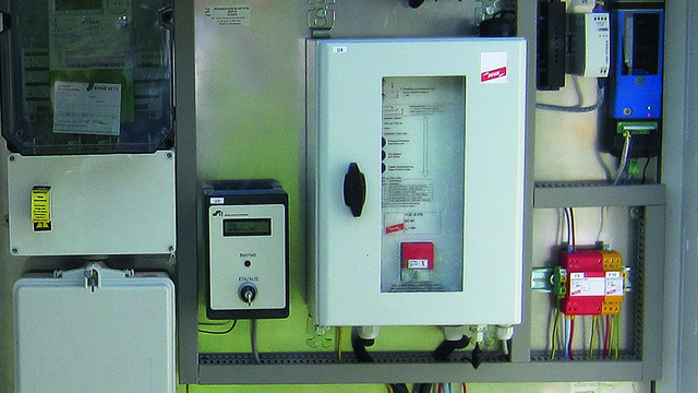
VCSD 40 IP65: Voltage-controlled smart decoupling device with adjustable response threshold
Description
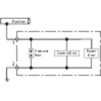
The smart decoupling device VCSD 40 IP65 is a short-circuiting switch which is controlled by overvoltage and limits long-duration, temporary and transient overvoltages. With the exception of direct currents, the VCSD is capable of discharging all interference voltages and limiting them to a preset value without negatively affecting the d.c. potential (cathodic protection potential). It limits the effects of dangerous high overvoltages in its immediate vicinity to a safe level.
Detail 1
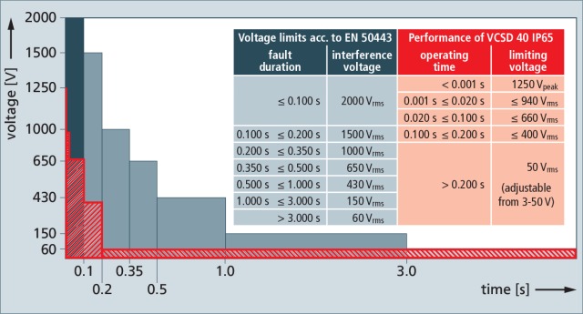
Limiting behaviour of VCSD 40 IP65 in the time range
Transient overvoltages are limited to values < 1.25 kV (time range: up to 1 ms).
Temporary overvoltages are limited to values < 940 V depending on the duration (time range: 1 ms to 200 ms).
Long-duration overvoltages are limited to values between 3 and 50 V a.c. (adjustable) (time range: > 200 ms).
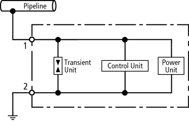
Functional description
Thanks to the coordinated and tested interaction of the functional units within the VCSD, the following overvoltage-related effects can be prevented:
Undefined, lightning-related puncture and flashover at insulating clearances
Lightning-related overvoltage is limited and the associated lightning currents are discharged to local earth.
Dangerous touch voltages at accessible places
Dangerous touch voltages are limited below the maximum permissible touch voltage for the duration of their occurrence.
Reduction of a.c. corrosion caused by a.c. interference
Technical alternating currents between 16.7 Hz and 60 Hz can be permanently discharged to low-impedance earth electrodes without negatively affecting the cathodic protection potential on long-distance pipelines.
Transient overvoltages are limited to values < 1.25 kV (time range: up to 1 ms).
Temporary overvoltages are limited to values < 940 V depending on the duration (time range: 1 ms to 200 ms).
Long-duration overvoltages are limited to values between 3 and 50 V a.c. (adjustable) (time range: > 200 ms).
Functional description
Thanks to the coordinated and tested interaction of the functional units within the VCSD, the following overvoltage-related effects can be prevented:
Undefined, lightning-related puncture and flashover at insulating clearances
Lightning-related overvoltage is limited and the associated lightning currents are discharged to local earth.
Dangerous touch voltages at accessible places
Dangerous touch voltages are limited below the maximum permissible touch voltage for the duration of their occurrence.
Reduction of a.c. corrosion caused by a.c. interference
Technical alternating currents between 16.7 Hz and 60 Hz can be permanently discharged to low-impedance earth electrodes without negatively affecting the cathodic protection potential on long-distance pipelines.
Detail 2
Monitoring / controlling
Due to the digital and analogue interfaces, the VCSD 40 IP65 can be externally controlled, device faults can be displayed and discharge currents can be signalled in the form of a 4 – 20 mA signal (scaled to 0 – 40 A).
Fields of application
The VCSD 40 IP65 is ideally suited for pipelines which are interfered by lightning strikes, electric railways or high-voltage lines. Typical fields of application are remote insulated pipeline sections, cathodically protected containers / storage tanks, open earthing of cable shields at accessible places or the corrosion-free interconnection of isolated earth-termination systems such as foundation earth electrodes of a building and an isolated signal ground or railway earth electrode.
Advantages of the VCSD 40 IP65 are the flexible and controllable use in different fields of application, the high discharge capacity as well as a tested, comprehensive, coordinated protection solution from the surge protection specialist DEHN.