BLITZDUCTOR® VT KKS

Combined lightning current and surge arrester for cathodic protection systems

Arrester for protecting active cathodic protection systems. Integrated floating remote signalling contact (break contact) monitors the function of the arrester.
  • Extremely efficient thanks to high discharge capacity
  • Easy maintenance due to remote signalling contact
  • Resistant to permanent interference voltages up to 65 V a.c.

Description

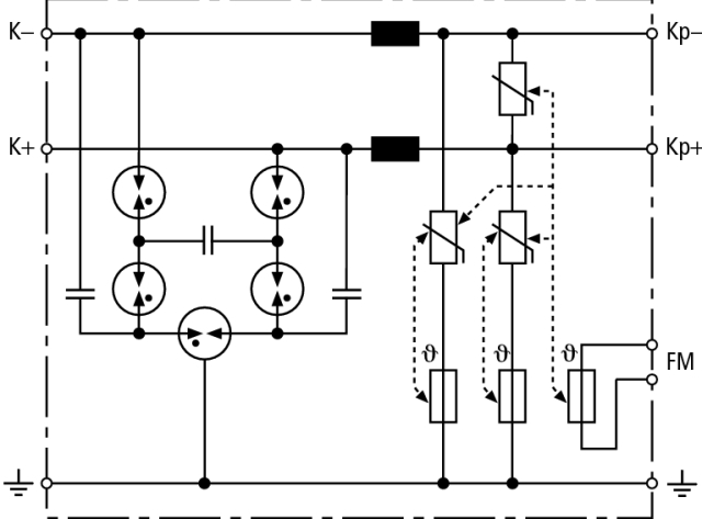
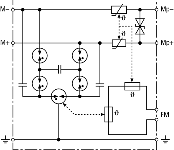
The protective circuit and voltage measuring circuit are protected against surges caused by atmospheric discharges (lightning strikes) or switching operations (in power supply lines).
The devices are designed for permanent interference voltages up to 65 V a.c. between pipelines and earth. If this value is exceeded, the relevant regulations concerning protection against electric shock have to be observed and further measures have to be taken.
The devices may be overloaded by overcurrents as a result of mains faults (short-circuits or earth faults). For this reason, they should be installed in a separate metal enclosure or a prewired terminal unit (ITAK) should be used. The integrated remote signalling contact indicates thermal overload of the discharge paths.
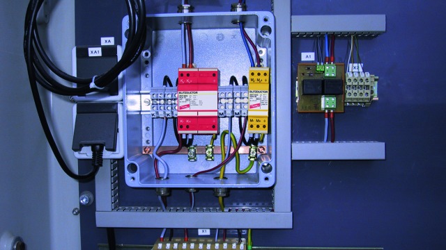
Detail 1

Different arresters for the protective circuit (red) and voltage measuring circuit (yellow).

Detail 2

The arresters for cathodic corrosion protection are equipped with a remote signalling contact.

Detail 3

Prewired unit (ITAK) for cathodic corrosion protection consisting of an arrester in a metal enclosure which protects the protective circuit and voltage measuring circuit.
Ordering designation: ITAK, serial No. 4305.

Models

BVT KKS ALD

BVT KKS APD

BVT KKS ALD

Basic circuit diagram BVT KKS ALDDimension drawing BVT KKS ALD

Energy-coordinated combined lightning current and surge arrester for protecting the rectifier in a protective circuit (red colour). Plug-in remote signalling contact (break contact) indicates overload (thermal monitoring of the varistors). Installation into steel-sheet enclosure recommended. A low impulse sparkover voltage is achieved by capacitive control.


Specifications

Type
Part No.
SPD class
Nominal voltage (UN)
Max. continuous operating voltage (d.c.) (Uc)
Nominal current (IL)
D1 Total lightning impulse current (10/350 µs) (Iimp)
D1 Lightning impulse current (10/350 µs) per line (Iimp)
C2 Total nominal discharge current (8/20 µs) (In)
C2 Nominal discharge current (8/20 µs) per line (In)
Voltage protection level line-line for Iimp D1 (Up)
Voltage protection level line-PG for Iimp D1 (Up)
Voltage protection level line-line at 1 kV/µs C3 (Up)
Voltage protection level line-PG at 1 kV/µs PG (Up)
A2 Total alternating current withstand capability
Series resistance per line
Cut-off frequency line-line (fG)
Capacitance line-line (C)
Capacitance line-PG (C)
Operating temperature range (TU)
Degree of protection
For mounting on
Connection (input / output)
Cross-sectional area, solid
Cross-sectional area, flexible
Tightening torque (terminal)
Earthing via
Enclosure material
Colour
Test standards
Approvals
Type of remote signalling contact
Switching capacity (d.c.)
Switching capacity (a.c.)
Cross-sectional area for remote signalling terminals
Weight
GTIN
PU
Part No.
  • BVT KKS ALD 75
  • 918 420
  • M
  • 70 V
  • 75 V
  • 12 A
  • 7 kA
  • 3.5 kA
  • 40 kA
  • 20 kA
  • ≤ 400 V
  • ≤ 400 V
  • ≤ 350 V
  • ≤ 350 V
  • 20 A
  • 5 µH
  • 1 MHz
  • ≤ 2 nF
  • ≤ 2 nF
  • -40 °C ... +80 °C
  • IP 20
  • 35 mm DIN rails acc. to EN 60715
  • screw / screw
  • 0.5-6 mm2
  • 0.5-4 mm2
  • 0.8 Nm
  • screw terminal
  • thermoplastic, UL 94 V-0
  • red
  • IEC 61643-21 / EN 61643-21
  • EAC
  • break contact
  • 250 V / 0.1 A, 125 V / 0.2 A, 75 V / 0.5 A
  • 250 V / 0.5 A
  • max 1.5 mm2
  • 212 g
  • 4013364094895
  • 1 pc(s)
  • 918 420
  • Specifications (PDF)
  • More
    • Further Pictures
      Basic circuit diagram BVT KKS ALD 75
      open PDF
      Dimension drawing BVT KKS ALD 75
      open PDF
      Further Information
      Product Specifications (Text)

      Back

      Coordinated combined arrester for protective circuits BVT KKS ALD 75
      Combined lightning current and surge arrester
      BLITZDUCTOR VT KKS, SPD class TYPE 1/P1,
      tested acc. to EN 61643-21 and energy coordinated 
      acc. to IEC 61643-22 for the protection of the
      inverter of cathodic corrosion protection systems, 
      with remote signalling contact, connection via 
      screw terminals, 2 pole, installation width 3 TE
      
      Max. continuous operating voltage (d.c.): 75 V
      Nominal current: 12 A
      D1 Total lightning impulse current (10/350 µs): 7 kA

      delivery and installation.

      Brand: DEHN
      Type: BVT KKS ALD 75
      Part No.: 918 420

      or equivalent.
      Installation Instructions
      Certificates
      CE_BVT_KKS_ALD_75

BVT KKS APD

Basic circuit diagram BVT KKS APDDimension drawing BVT KKS APD

Energy-coordinated combined lightning current and surge arrester for protecting voltage measuring circuits (yellow colour). Plug-in remote signalling contact (break contact) indicates overload (thermal monitoring of the discharge paths). Installation into steel-sheet enclosure recommended. A low impulse sparkover voltage is achieved by capacitive control.


Specifications

Type
Part No.
SPD class
Nominal voltage (UN)
Max. continuous operating voltage (d.c.) (Uc)
Nominal current (IL)
D1 Total lightning impulse current (10/350 µs) (Iimp)
D1 Lightning impulse current (10/350 µs) per line (Iimp)
C2 Total nominal discharge current (8/20 µs) (In)
C2 Nominal discharge current (8/20 µs) per line (In)
Voltage protection level line-line for Iimp D1 (Up)
Voltage protection level line-PG for Iimp D1 (Up)
Voltage protection level line-line at 1 kV/µs C3 (Up)
Voltage protection level line-PG at 1 kV/µs PG (Up)
A2 Total alternating current withstand capability
Series resistance per line
Cut-off frequency line-line (fG)
Capacitance line-line (C)
Capacitance line-PG (C)
Operating temperature range (TU)
Degree of protection
For mounting on
Connection (input / output)
Cross-sectional area, solid
Cross-sectional area, flexible
Tightening torque (terminal)
Earthing via
Enclosure material
Colour
Test standards
Approvals
Type of remote signalling contact
Switching capacity (d.c.)
Switching capacity (a.c.)
Cross-sectional area for remote signalling terminals
Weight
GTIN
PU
Part No.
  • BVT KKS APD 36
  • 918 421
  • M
  • 36 V
  • 36.8 V
  • 0.05 A
  • 7 kA
  • 3.5 kA
  • 40 kA
  • 20 kA
  • ≤ 65 V
  • ≤ 800 V
  • ≤ 48 V
  • ≤ 600 V
  • 20 A
  • 55 ohms
  • 4 dB at 1 MHz (100 ohms)
  • ≤ 1 nF
  • ≤ 10 pF
  • -40 °C ... +80 °C
  • IP 20
  • 35 mm DIN rails acc. to EN 60715
  • screw / screw
  • 0.5 mm-6 mm2
  • 0.5 mm-4 mm2
  • 0.8 Nm
  • screw terminal
  • thermplastic, UL 94 V-0
  • yellow
  • IEC 61643-21 / EN 61643-21
  • EAC
  • break contact
  • 250 V / 0.1 A, 125 V / 0.2 A, 75 V / 0.5 A
  • 250 V / 0.5 A
  • max. 1.5 mm2
  • 118 g
  • 4013364094901
  • 1 pc(s)
  • 918 421
  • Specifications (PDF)
  • More
    • Further Pictures
      Basic circuit diagram BVT KKS APD 36
      open PDF
      Dimension drawing BVT KKS APD 36
      open PDF
      Further Information
      Product Specifications (Text)

      Back

      Coordinated combined arrester for voltage measuring circuits BVT KKS APD 36
      Combined lightning current and surge arrester
      BLITZDUCTOR VT KKS, SPD class TYPE 1/P1,
      tested acc. to EN 61643-21 and energy coordinated 
      acc. to IEC 61643-22 for the protection of voltage 
      measuring circuits of cathodic corrosion protection 
      systems, with remote signalling contact, connection 
      via screw terminals, 2 pole, installation width 1,5 TE
      
      Max. continuous operating voltage (d.c.): 36.8 V
      Nominal current: 0.05 A
      D1 Total lightning impulse current (10/350 µs): 7 kA

      delivery and installation.

      Brand: DEHN
      Type: BVT KKS APD 36
      Part No.: 918 421

      or equivalent.
      Installation Instructions
      Certificates
      CE_BVT_KKS_APD_36