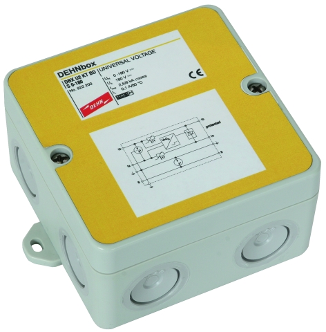
DEHNbox

Universal Lightning Current / Surge Arrester

DEHNbox used for a telecommunication connection (example: Uk0interface)
    Combined lightning current and surge arrester
  • Capable of carrying lightning currents up to 10 kA (10/350 µs)
  • Low voltage protection level, capable of protecting terminal equipment
  • For installation in conformity with the lightning protection zone concept at the boundaries from 0A – 2 and higher
  • Easy to use
  • Suitable for wall mounting, IP 65 degree of protection
  • Fast and easy installation due to spring-loaded terminals
  • Easy retrofitting of surge protection

Description

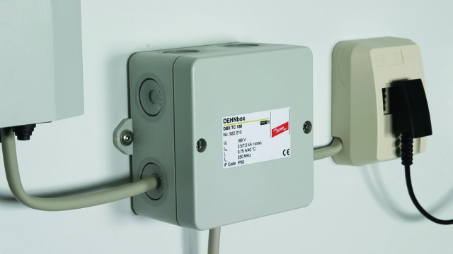
The compact arresters of the DEHNbox product family are combined lightning current and surge arresters designed for protecting information, measuring and control and automation equipment and systems. With its surface-mounted plastic enclosure with integrated fixing lugs, DEHNbox is ideally suited for wall mounting and can be easily retrofitted into existing equipment and systems. The IP 65 degree of protection allows the arrester to be used in harsh environments such as in moist atmospheres. The conductors are therefore entered via easy-to-install self-sealing rubber grommets. These grommets allow easy and fast installation and prevent the ingress of moisture and dust. Both the cores and an installed line shield can be contacted by means of spring-loaded terminals without the use of screws. DEHNbox is available in two versions:
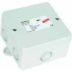
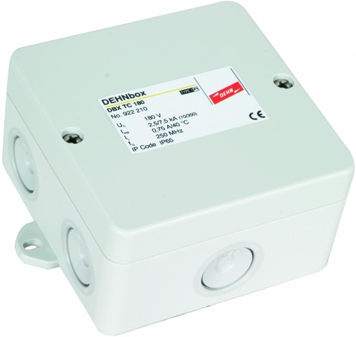
DEHNbox TC 180
The arrester is optimised for use at telecommunication connections and devices such as analogue telephones as well as ISDN and VDSL2 connections. With a cut-off frequency of 250 MHz, the arrester is also capable of transmitting high-frequency signal parts and can thus be used at high-performance signal interfaces. As an alternative, DEHNbox TC 180 can also be installed at measuring and control interfaces up to a voltage of 180 V and a maximum current of 750 mA.
DEHNbox TC 180 allows fast connection of one pair without tools and fixing of the connecting cable (integrated strain relief) on the printed circuit board by means of cable ties. The connection space in the box and the position of the terminals ensure optimal conductor routing and easy conductor connection.

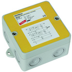
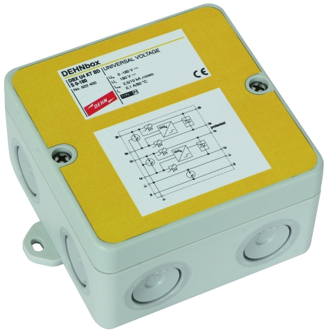
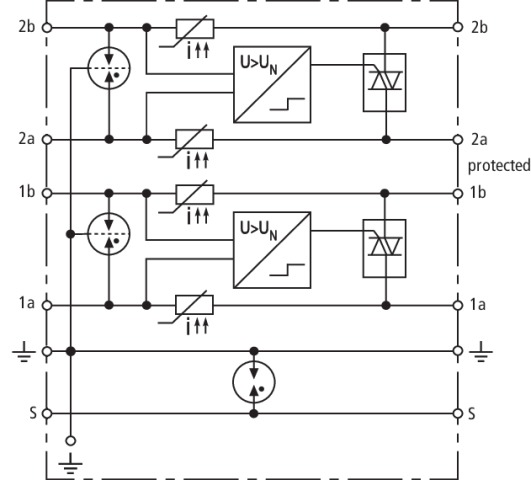
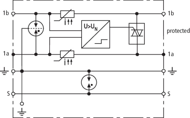
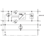
DEHNbox with actiVsense technology
This arrester type does not have a specific nominal voltage and can thus be used for voltages ranging from 0 to 180 V with a superimposed signal voltage (± 5 V/50 MHz). The nominal current is limited to 100 mA which is sufficient for information technology systems. This innovative actiVsense technology allows the arrester to detect the signal voltage applied and to automatically adapt the voltage protection level to this voltage. This makes the arrester ideal for applications where changing or slowly fluctuating signal levels (≤ 400 Hz) are to be expected. In case of interference, DEHNbox arresters have an adapted voltage protection level for every signal voltage, thus providing maximum protection for the devices and system circuits connected to them. The four-pole version of DEHNbox provides protection for two different balanced interfaces, e.g. a bus interface with a system voltage of 5 V and an analogue measured value signal with a system voltage of 24 V.
The arrester is ideally suited for domestic and industrial use in information technology transmission systems such as telecommunication, bus and measuring and control systems.

Detail 1

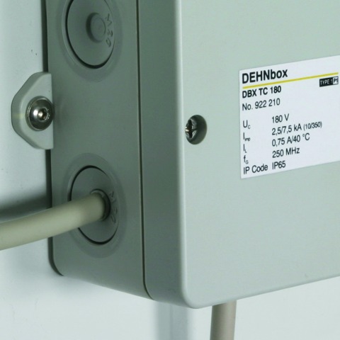
Cable entry with self-sealing rubber grommets.

Detail 2

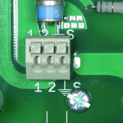
Conductor terminals for fast connection without tools (DBX TC 180).

Detail 3

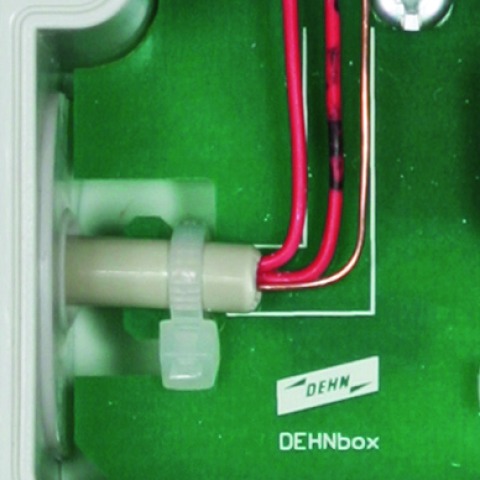
Conductor fixing by means of cable ties (DBX TC 180).

Detail 4

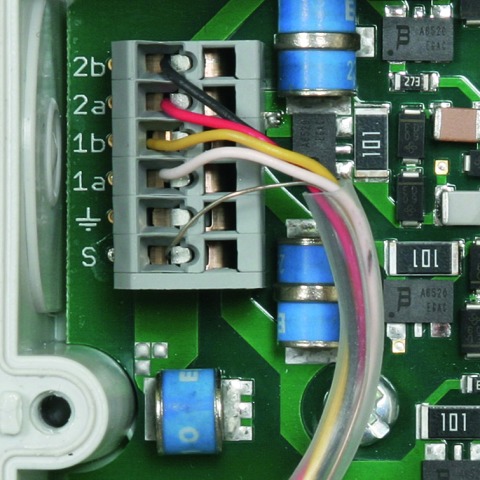
Available with direct or indirect shield earthing (DBX U4/U2 KT BD S 0-180).
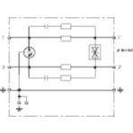
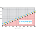
Detail 5

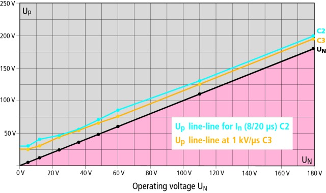
Voltage protection level diagram (DBX U4/U2 KT BD S 0-180)

Models

DBX TC 180

DBX U4 KT BD S 0-180

,DBX U2 KT BD S 0-180

DBX TC 180

Basic circuit diagram DBX TC 180Dimension drawing DBX TC 180

Compact combined arrester in a surface-mounted plastic enclosure for protecting information technology interfaces, particularly telecommunication connections and devices such as analogue telephones, ISDN and xDSL (VDSL2-tested). Fast connection of one pair without tools and integrated strain relief for the connecting cable. Cut-off frequency up to 250 MHz ensures maximum transmission performance in case of high-frequency signal parts.


Specifications

Type
Part No.
SPD class
Nominal voltage (UN)
Max. continuous operating voltage (d.c.) (UC)
Max. continuous operating voltage (a.c.) (UC)
Nominal current at 45°C (IL)
D1 Total lightning impulse current (10/350 µs) ( Iimp)
D1 Lightning impulse current (10/350 µs) per line ( Iimp)
C2 Total nominal discharge current (8/20 µs) ( In)
C2 Nominal discharge current (8/20 µs) per line ( In)
Voltage protection level line-line at 1 kV/µs C3 (Up)
Voltage protection level line-PG at 1 kV/µs C3 (Up)
Voltage protection level line-line for Iimp D1 (Up)
Voltage protection level line-PG for Iimp D1 (UP)
Series resistance per line
Bandwidth line-line (100 ohms) (fG)
Capacitance line-line (C)
Capacitance line-PG (C)
Operating temperature range (TU)
Degree of protection
Cross-sectional area of the signal lines, solid
Cross-sectional area of the signal lines, flexible
Cross-sectional area of the earth terminal
Dimensions (L x W x H)
Enclosure material
Colour
Test standards
Weight
GTIN
PU
Part No.
  • DBX TC 180
  • 922 210
  • L
  • 180 V
  • 180 V
  • 127 V
  • 0.75 A
  • 7.5 kA
  • 2.5 kA
  • 15 kA
  • 7.5 kA
  • ≤ 250 V
  • ≤ 550 V
  • ≤ 300 V
  • ≤ 550 V
  • 1.8 ohms
  • 250 MHz
  • ≤ 20 pF
  • ≤ 10 pF
  • -25 °C ... +40 °C
  • IP 65
  • 0.2-1.5 mm2
  • 0.25-1.5 mm2
  • 0.25-2.5 mm2
  • 93 x 93 x 55 mm
  • polycarbonate
  • grey
  • IEC 61643-21 / EN 61643-21
  • 138 g
  • 4013364158214
  • 1 pc(s)
  • 922 210
  • Specifications (PDF)
  • More

DBX U4 KT BD S 0-180

Basic circuit diagram DBX U4 KT DB S 0-180Dimension drawing DBX U4 KT DB S 0-180

Compact combined lightning current and surge arrester in a surface-mounted plastic enclosure with actiVsense technology for protecting two pairs with the same or a different signal voltage of galvanically isolated balanced interfaces. Direct or indirect shield earthing.


Specifications

Type
Part No.
SPD class
Nominal voltage (UN)
Frequency of the nominal voltage (fUN)
Max. continuous operating voltage (d.c.) (UC)
Permissible superimposed signal voltage (Usignal)
Cut-off frequency line-line (Usignal, balanced 100 ohms) (fG)
Nominal current IL (equals max. short-circuit current)
D1 Total lightning impulse current (10/350 µs) ( Iimp)
D1 Lightning impulse current (10/350 µs) per line ( Iimp)
C2 Total nominal discharge current (8/20 µs) ( In)
C2 Nominal discharge current (8/20 µs) per line ( In)
Voltage protection level line-line for In C2 (Up)
Voltage protection level line-line at 1 kV/µs C3 (Up)
Voltage protection level line-line for Iimp D1 (Up)
Voltage protection level line-PG for D1/C2/C3
Series resistance per line
Capacitance line-line (C)
Capacitance line-PG (C)
Operating temperature range (TU)
Degree of protection
Cross-sectional area of the signal lines
Cross-sectional area of the earth terminal
Dimensions (L x W x H)
Enclosure material
Colour
Test standards
Approvals
Weight
GTIN
PU
Part No.
  • DBX U4 KT BD S 0-180
  • 922 400
  • M
  • 0-180 V
  • 0-400 Hz
  • 180 V
  • ≤ +/- 5 V
  • 50 MHz
  • 100 mA
  • 10 kA
  • 2.5 kA
  • 20 kA
  • 10 kA
  • see diagram, line C2
  • see diagram, line C3
  • ≤ UN + 50 V
  • ≤ 550 V
  • ≤ 9 ohms; typically 7.9 ohms
  • ≤ 80 pF
  • ≤ 70 pF
  • -25 °C ... +40 °C
  • IP 65
  • 0.08-1.5 mm2
  • 2.5-4 mm2
  • 93 x 93 x 55 mm
  • polycarbonate
  • grey
  • IEC 61643-21 / EN 61643-21
  • EAC
  • 220 g
  • 4013364137349
  • 1 pc(s)
  • 922 400
  • Specifications (PDF)
  • More
    • Further Pictures
      Basic circuit diagram DBX U4 KT DB S 0-180
      open PDF
      Voltage protection level diagram DBX
      open PDF
      Further Information
      Product Specifications (Text)

      Back

      Compact DEHNbox DBX U4 KT BD S 0-180 combined arrester
      Universal type 1/P1 lightning current and surge  
      arrester with actiVsense technology 
      for automatic detection of the operating voltage 
      and optimal adaptation of the voltage protection 
      level; tested to EN 61643-21 and energy-coordinated 
      according to IEC 61643-22 for protecting one pair
      for galvanically isolated balanced interfaces,
      optional direct or indirect shield earthing
      Operating voltage: UN: 0-180 V 
      Permissible superimposed signal voltage: ≤ +/- 5 V
      Nominal current IL (equals max. short-circuit current): 100 mA
      D1 Total lightning impulse current (10/350 µs): 10 kA
      C2 Total nominal discharge current (8/20 µs): 20 kA

      delivery and installation.

      Brand: DEHN
      Type: DBX U4 KT BD S 0-180
      Part No.: 922 400

      or equivalent.
      Installation Instructions
      Certificates
      CE_DBX_U4_KT_BD_S_0_180
      CAD-Data for registered Users
      922210.stp
      922210.igs
      922210.jt
      922210.dwg
      922200_400m_D.dxf

,DBX U2 KT BD S 0-180

Basic circuit diagram DBX U2 KT DB S 0-180Dimension drawing DBX U2 KT DB S 0-180

Compact combined lightning current and surge arrester in a surface-mounted plastic enclosure with actiVsense technology for protecting one pair of galvanically isolated balanced interfaces. Direct or indirect shield earthing.


Specifications

Type
Part No.
SPD class
Nominal voltage (UN)
Frequency of the nominal voltage (fUN)
Max. continuous operating voltage (d.c.) (UC)
Permissible superimposed signal voltage (Usignal)
Cut-off frequency line-line (Usignal, balanced 100 ohms) (fG)
Nominal current IL (equals max. short-circuit current)
D1 Total lightning impulse current (10/350 µs) ( Iimp)
D1 Lightning impulse current (10/350 µs) per line ( Iimp)
C2 Total nominal discharge current (8/20 µs) ( In)
C2 Nominal discharge current (8/20 µs) per line ( In)
Voltage protection level line-line for In C2 (Up)
Voltage protection level line-line at 1 kV/µs C3 (Up)
Voltage protection level line-line for Iimp D1 (Up)
Voltage protection level line-PG for D1/C2/C3
Series resistance per line
Capacitance line-line (C)
Capacitance line-PG (C)
Operating temperature range (TU)
Degree of protection
Cross-sectional area of the signal lines
Cross-sectional area of the earth terminal
Dimensions (L x W x H)
Enclosure material
Colour
Test standards
Approvals
Weight
GTIN
PU
Part No.
  • DBX U2 KT BD S 0-180
  • 922 200 ,
  • M
  • 0-180 V
  • 0-400 Hz
  • 180 V
  • ≤ +/- 5 V
  • 50 MHz
  • 100 mA
  • 9 kA
  • 2.5 kA
  • 20 kA
  • 10 kA
  • see diagram, line C2
  • see diagram, line C3
  • ≤ UN + 50 V
  • ≤ 550 V
  • ≤ 9 ohms; typically 7.9 ohms
  • ≤ 80 pF
  • ≤ 70 pF
  • -25 °C ... +40 °C
  • IP 65
  • 0.08-1.5 mm2
  • 2.5-4 mm2
  • 93 x 93 x 55 mm
  • polycarbonate
  • grey
  • IEC 61643-21 / EN 61643-21
  • EAC
  • 142 g
  • 4013364137332
  • 1 pc(s)
  • 922 200
  • Specifications (PDF)
  • More
    • Further Pictures
      Basic circuit diagram DBX U2 KT DB S 0-180
      open PDF
      Voltage protection level diagram DBX
      open PDF
      Further Information
      Product Specifications (Text)

      Back

      Compact DEHNbox DBX U2 KT BD S 0-180 combined arrester
      Universal lightning current and surge arrester 
      SPD class: type 1/P1 with actiVsense technology 
      for automatic detection of the operating voltage 
      and optimal adaptation of the voltage protection 
      level; tested to EN 61643-21 and energy-coordinated 
      according to IEC 61643-22 for protecting one pair
      for galvanically isolated balanced interfaces,
      optional direct or indirect shield earthing
      Operating voltage: UN: 0-180 V 
      Permissible superimposed signal voltage: ≤ +/- 5 V
      Nominal current IL (equals max. short-circuit current): 100 mA
      D1 Total lightning impulse current (10/350 µs): 9 kA
      C2 Total nominal discharge current (8/20 µs): 20 kA

      delivery and installation.

      Brand: DEHN
      Type: DBX U2 KT BD S 0-180
      Part No.: 922 200

      or equivalent.
      Certificates
      CE_DBX_U2_KT_BD_S_0_180
      CAD-Data for registered Users
      922210.stp
      922210.igs
      922210.jt
      922210.dwg
      922200_400m_D.dxf