DEHNpipe

Surge Arrester

Surge arrester for outdoor use to be screwed onto two-wire field devices. Stainless steel, installation with cable gland up to IP 67.
    Surge arresters to be screwed onto field devices
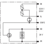
  • Parallel or series connection
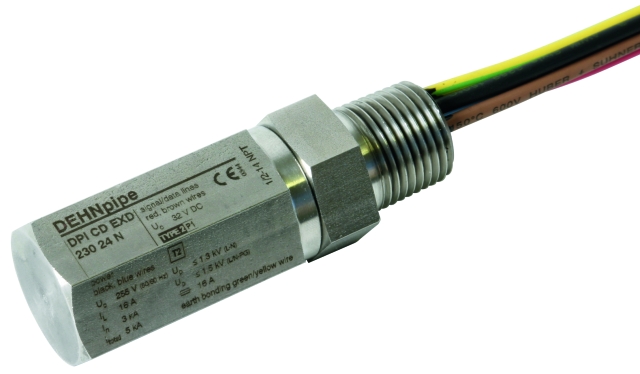
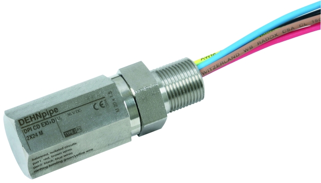
  • Made of corrosion-resistant stainless steel
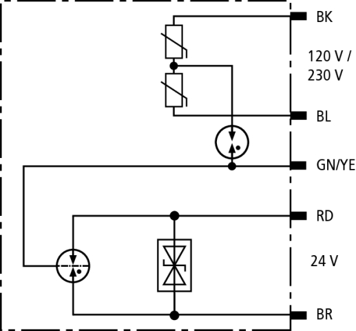
  • Arrester for protecting a second interface (data or power side) available
  • Types for Ex (i) and Ex (d) applications
  • For protecting intrinsically safe measuring circuits and bus systems Ex (i)
  • Type in a flameproof enclosure Ex (d)
  • Variety of approvals
  • Approvals depending on the arrester: IECEx, ATEX, FISCO, CSA Hazloc

Description

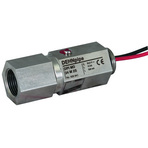
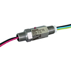
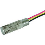
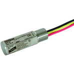
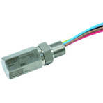
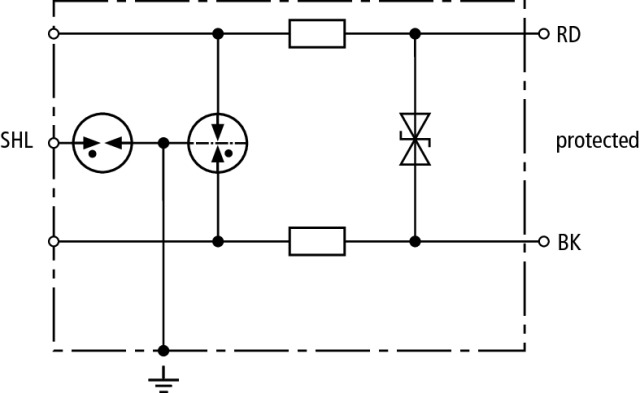
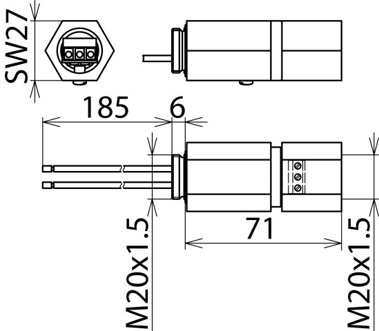
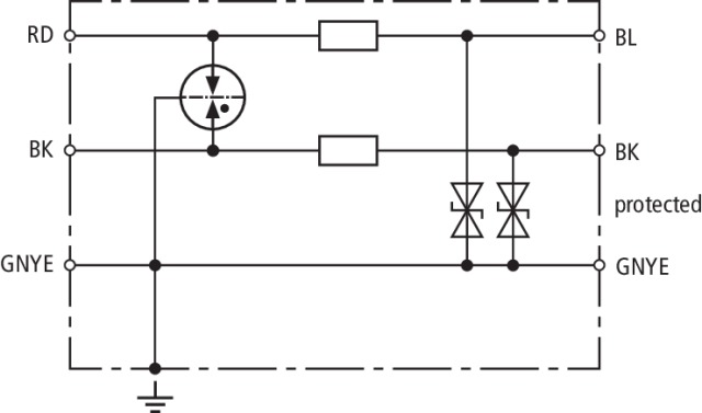
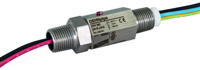
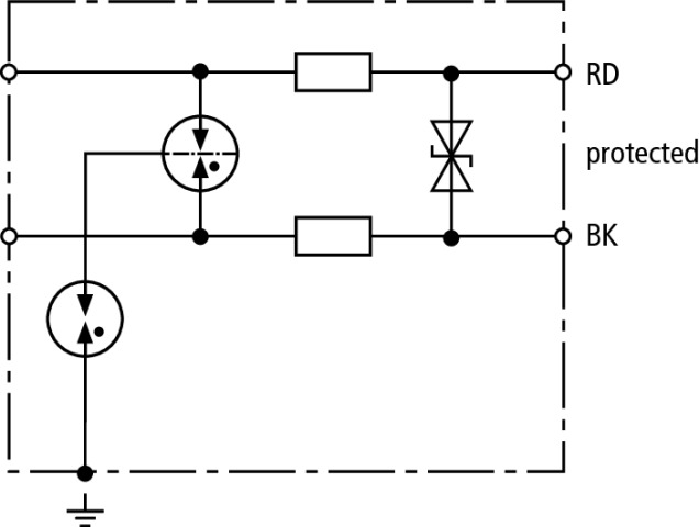
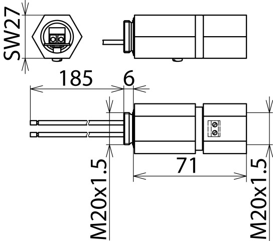
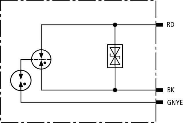
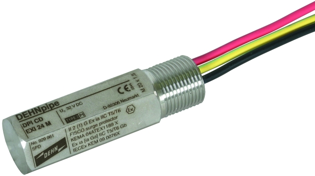
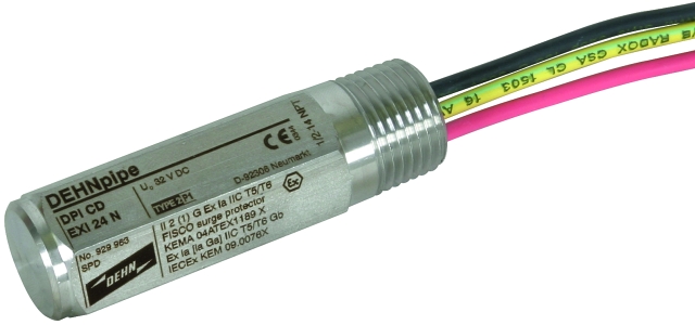
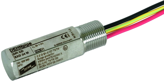
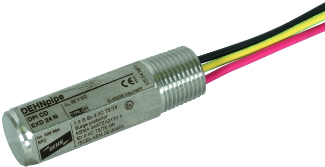
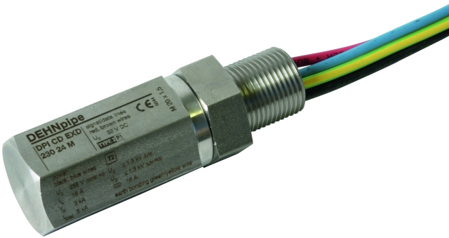
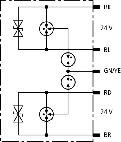
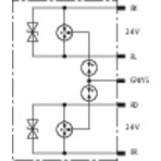
The devices of the DEHNpipe family are made of corrosion-resistant stainless steel and can be directly screwed onto a field device. The permanently connected lines are connected to the terminals of the field device. Surge protective devices for series connection and parallel connection are available. Arresters for series connection are located directly in the cable run which ensures energy coordination with other arresters. These arresters can also be used for field devices with a single field device terminal or a single cable gland. Arresters for parallel connection are attached to the spare cable gland of the field devices or in the field bus distributor and are situated in parallel to the cable run. Due to their design, both versions have an IP 67 degree of protection.

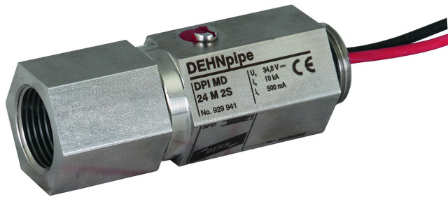
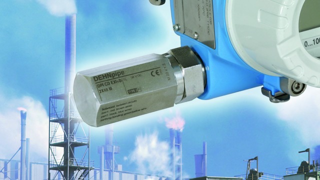
Ex(i) und Ex(d) versions are available for field devices in potentially explosive atmospheres. Depending on the type, the arresters can thus be installed on field devices in intrinsically safe measuring circuits Ex(i) or on devices with flameproof enclosure and are suitable for use in Ex zone 1 or 2.

The surge arresters are ideally suited for installation in process environments, for example on transducers or field bus devices. 4-20 mA measuring circuits or bus systems up to 30 V are typical fields of application.
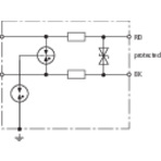
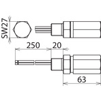
Detail 1

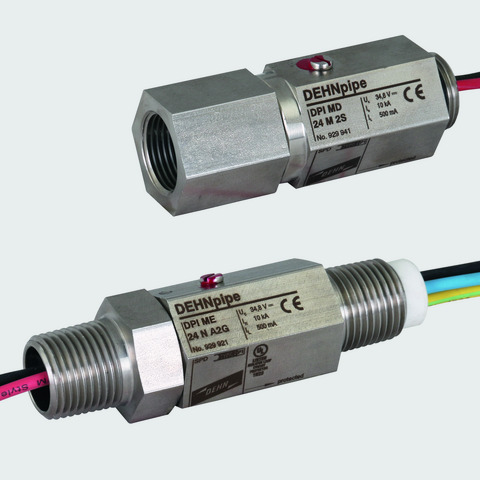
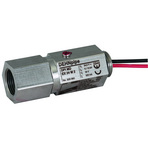
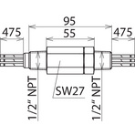
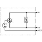
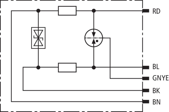
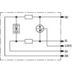
Types for series connection.
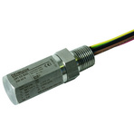
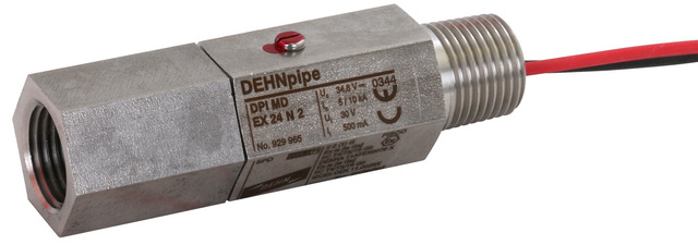
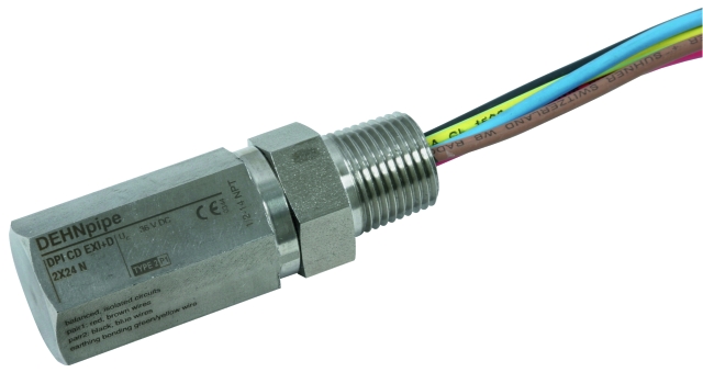
Detail 2

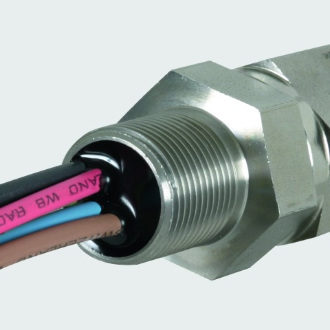
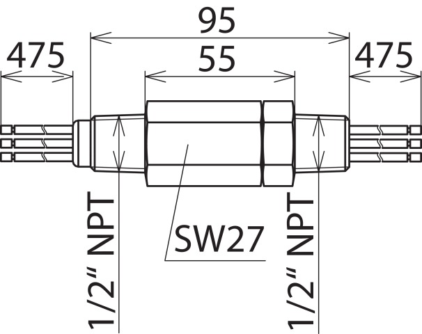
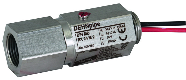
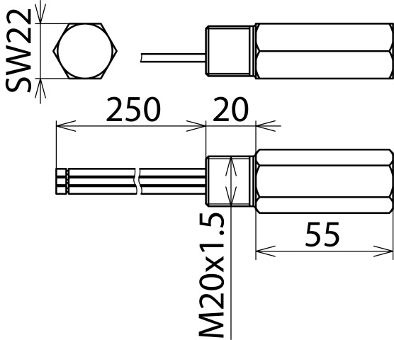
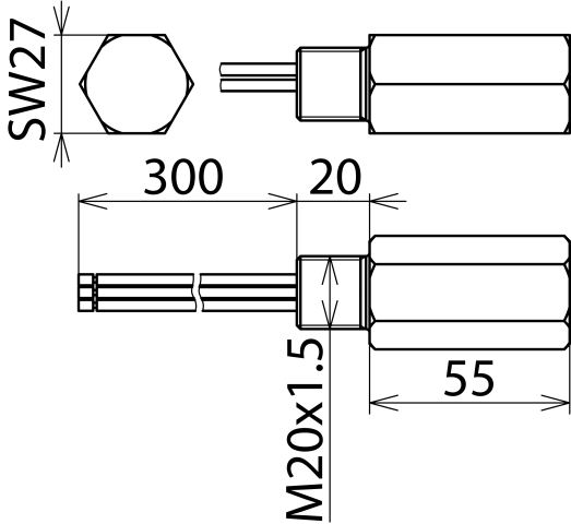
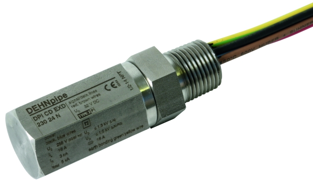
Robust type made of corrosion-resistant stainless steel.
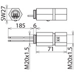
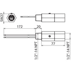
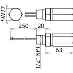
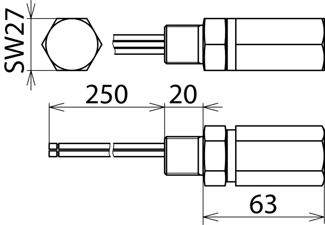
Detail 3

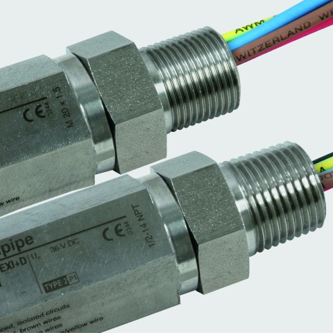
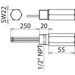
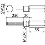
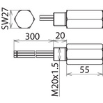
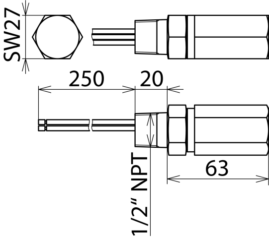
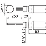
Metric and NPT thread.

Detail 4

ATEX and IECEx approval.

Models

DPI MD

DPI ME

DPI MD EX

DPI CD EXI

DPI CD EXD

DPI CD HF EXD

DPI CD EXD 230 24

DPI CD EXI+D 2X24

DPI MD

Basic circuit diagram DPI MDDimension drawing DPI MD

Energy-coordinated two-stage arrester, no leakage currents to earth, for 4-20 mA interfaces with M20 x 1.5 thread (female/male). Direct, indirect or no shield earthing. Cable gland available as accessory part.


Specifications

Type
Part No.
SPD class
Nominal voltage (UN)
Max. continuous operating voltage (d.c.) (UC)
Max. continuous operating voltage (a.c.) (UC)
Nominal current (IL)
D1 Lightning impulse current (10/350 µs) per line (Iimp)
C2 Total nominal discharge current (8/20 µs) (In)
C2 Nominal discharge current (8/20 µs) per line (In)
C2 Nominal discharge current (8/20 µs) shield-PG (In)
Voltage protection level line-line for In C2 (Up)
Voltage protection level line-PG for In C2 (UP)
Voltage protection level shield-PG for In C2 (UP)
Voltage protection level line-line at 1 kV/µs C3 (UP)
Voltage protection level line-PG at 1 kV/µs C3 (UP)
Voltage protection level shield-PG at 1 kV/µs C3 (UP)
Cut-off frequency line-line (fG)
Capacitance line-line (C)
Capacitance line-PG (C)
Capacitance shield-PG (C)
Series resistance per line
Operating temperature range (TU)
Degree of protection with cable gland
For mounting on (field / device side)
Connection (input / output)
Length of the connecting lead
Cross-sectional area, solid
Cross-sectional area, flexible
Earthing via
Enclosure material
Colour
Test standards
Approvals
SIL classification
Weight
GTIN
PU
Part No.
*) For details see: www.dehn-international.com
  • DPI MD 24 M 2S
  • 929 941
  • Q
  • 24 V
  • 34.8 V
  • 24.5 V
  • 0.5 A
  • 1 kA
  • 10 kA
  • 10 kA
  • 20 kA
  • ≤ 65 V
  • ≤ 650 V
  • ≤ 650 V
  • ≤ 50 V
  • ≤ 500 V
  • ≤ 600 V
  • 14 MHz
  • ≤ 400 pF
  • ≤ 20 pF
  • ≤ 15 pF
  • 2.2 ohms
  • -40 °C ... +80 °C
  • IP 67
  • M20 x 1.5 female thread / M20 x 1.5 male thread
  • screw / connecting lines (1.5 mm2)
  • 200 mm
  • 0.08-2.5 mm2
  • 0.08-1.5 mm2
  • enclosure or earthing ring (accessories)
  • StSt (V2A)
  • bare surface
  • IEC 61643-21 / EN 61643-21
  • EAC, SIL
  • up to SIL3 *)
  • 173 g
  • 4013364098152
  • 1 pc(s)
  • 929 941
  • Specifications (PDF)
  • More

DPI ME

Basic circuit diagram DPI MEDimension drawing DPI ME

Energy-coordinated two-stage arrester with gas discharge tube and diodes to earth. For unbalanced interfaces with 1/2-14 NPT thread (male/male). The earthing conductor is led through the surge arrester.


Specifications

Type
Part No.
SPD class
Nominal voltage (UN)
Max. continuous operating voltage (d.c.) (UC)
Max. continuous operating voltage (a.c.) (UC)
Nominal current (IL)
D1 Lightning impulse current (10/350 µs) per line (Iimp)
C2 Total nominal discharge current (8/20 µs) (In)
C2 Nominal discharge current (8/20 µs) per line (In)
Voltage protection level line-line for In C2 (Up)
Voltage protection level line-PG for In C2 (UP)
Voltage protection level line-line at 1 kV/µs C3 (UP)
Voltage protection level line-PG at 1 kV/µs C3 (UP)
Capacitance line-line (C)
Capacitance line-PG (C)
Series resistance per line
Operating temperature range (TU)
Degree of protection
For mounting on (field / device side)
Connection (input / output)
Length of the connecting lead
Earthing via
Enclosure material
Colour
Test standards
Approvals
SIL classification
Weight
GTIN
PU
Part No.
*) For details see: www.dehn-international.com

DPI MD EX

Basic circuit diagram DPI MD EXDimension drawing DPI MD EX

Energy-coordinated two-stage surge arrester with low-capacitance protective circuit for protecting intrinsically safe measuring circuits and bus systems, meets FISCO requirements. Insulation strength > 500 V to earth. Cable glands must be ordered separately.


Specifications

Type
Part No.
SPD class
Nominal voltage (UN)
Max. continuous operating voltage (d.c.) (UC)
Max. continuous operating voltage (a.c.) (UC)
Max. input voltage acc. to EN 60079-11 (Ui)
Max. input current acc. to EN 60079-11 (Ii)
Nominal current (IL)
D1 Lightning impulse current (10/350 µs) per line (Iimp)
C2 Total nominal discharge current (8/20 µs) (In)
C2 Nominal discharge current (8/20 µs) per line (In)
Voltage protection level line-line for In C2 (Up)
Voltage protection level line-PG for In C2 (UP)
Voltage protection level line-line at 1 kV/µs C3 (UP)
Voltage protection level line-PG at 1 kV/µs C3 (UP)
Cut-off frequency line-line (fG)
Capacitance line-line (C)
Capacitance line-PG (C)
Series resistance per line
Operating temperature range (TU)
Degree of protection
For mounting on (field / device side)
Connection (input / output)
Length of the connecting lead
Cross-sectional area, solid
Cross-sectional area, flexible
Earthing via
Enclosure material
Colour
Test standards
Approvals
ATEX approvals
IECEx approvals
SIL classification
Weight
GTIN
PU
Part No.
*) For details see: www.dehn-international.com
  • DPI MD EX 24 M 2
  • 929 960
  • T
  • 24 V
  • 34.8 V
  • 24.5 V
  • 30 V
  • 0.5 A
  • 0.5 A
  • 1 kA
  • 10 kA
  • 5 kA
  • ≤ 55 V
  • ≤ 1100 V
  • ≤ 49 V
  • ≤ 1000 V
  • 7 MHz
  • ≤ 850 pF
  • ≤ 15 pF
  • 1.8 ohms
  • -40 °C ... +80 °C
  • IP 67
  • M20 x 1.5 female thread / M20 x 1.5 male thread
  • screw / connecting lines (1.5 mm2)
  • 200 mm
  • 0.08-2.5 mm2
  • 0.08-1.5 mm2
  • enclosure
  • StSt (V2A)
  • bare surface
  • IEC 61643-21 / EN 61643-21
  • EACEx, ATEX, IECEx, SIL
  • DEKRA 11ATEX0076 X: II 2 (1) G Ex ia [ia Ga] IIC T4 ... T6 Gb
  • DEK 11.0025X: Ex ia [ia Ga] IIC T4 ... T6 Gb
  • up to SIL3 *)
  • 172 g
  • 4013364098145
  • 1 pc(s)
  • 929 960
  • Specifications (PDF)
  • More
  • DPI MD EX 24 N 2
  • 929 965
  • T
  • 24 V
  • 34.8 V
  • 24.5 V
  • 30 V
  • 0.5 A
  • 0.5 A
  • 1 kA
  • 10 kA
  • 5 kA
  • ≤ 55 V
  • ≤ 1100 V
  • ≤ 49 V
  • ≤ 1000 V
  • 7 MHz
  • ≤ 850 pF
  • ≤ 15 pF
  • 1.8 ohms
  • -40 °C ... +80 °C
  • IP 67
  • 1/2-14 NPT female thread / 1/2-14 NPT male thread
  • screw / connecting lines (1.5 mm2)
  • 200 mm
  • 0.08-2.5 mm2
  • 0.08-1.5 mm2
  • enclosure
  • NIRO (V2A)
  • bare
  • IEC 61643-21 / EN 61643-21
  • ATEX, IECEx, SIL
  • DEKRA 11ATEX0076 X: II 2 (1) G Ex ia [ia Ga] IIC T4 ... T6 Gb
  • DEK 11.0025X: Ex ia [ia Ga] IIC T4 ... T6 Gb
  • up to SIL3 *)
  • 171 g
  • 4013364360778
  • 1 pc(s)
  • 929 965
  • Specifications (PDF)
  • More
    • Further Pictures
      Basic circuit diagram DPI MD EX 24 N 2
      open PDF
      Dimension drawing DPI MD EX 24 N 2
      open PDF
      Further Information
      Product Specifications (Text)

      Back

      Coordinated two-stage arrester DEHNpipe DPI MD EX 24 N 2
      Surge arrester DEHNpipe, SPD class TYPE 2/1, 
      tested acc. to EN 61643-21 and energy coordinated
      acc. to IEC 61643-22, in V2A, IP67, two-part
      enclosure design in Ex(i) version, for screwing 
      into 2-conductor process field devices, for serial 
      protection of intrinsically safe interfaces acc. to 
      NAMUR NE 21
      
      Max. continuous operating voltage (d.c.): 34.8 V
      Nominal current: 0.5 A
      C2 Total nominal discharge current (8/20 µs): 10 kA
      Cut-off frequency line-line: 7 MHz

      delivery and installation.

      Brand: DEHN
      Type: DPI MD EX 24 N 2
      Part No.: 929 965

      or equivalent.
      Installation Instructions
      Certificates
      DEKRA 11ATEX0076 X
      IECEx DEK 11_0025X
      CE_DPI_MD_EX_24_N_2
      CAD-Data for registered Users
      929965.dxf

DPI CD EXI

Basic circuit diagram DPI CD EXIDimension drawing DPI CD EXI

Surge arrester with a low-capacitance protective circuit for protecting intrinsically safe measuring circuits and bus systems, meets FISCO requirements. Insulation strength > 500 V to earth.


Specifications

Type
Part No.
SPD class
Nominal voltage (UN)
Max. continuous operating voltage (d.c.) (UC)
Max. continuous operating voltage (a.c.) (UC)
Max. input voltage acc. to EN 60079-11 (Ui)
Max. input current acc. to EN 60079-11 (Ii)
Nominal current (IL)
D1 Lightning impulse current (10/350 µs) line-PG (Iimp)
C2 Total nominal discharge current (8/20 µs) (In)
C2 Nominal discharge current (8/20 µs) line-line (In)
C2 Nominal discharge current (8/20 µs) line-PG (In)
Voltage protection level line-line for In C2 (Up)
Voltage protection level line-PG for In C2 (UP)
Voltage protection level line-line at 1 kV/µs C3 (UP)
Voltage protection level line-PG at 1 kV/µs C3 (UP)
Cut-off frequency line-line (fG)
Capacitance line-line (C)
Capacitance line-PG (C)
Operating temperature range (TU)
Degree of protection
For mounting on (field / device side)
Connection
Length of the connecting lead
Earthing via
Enclosure material
Colour
Test standards
Approvals
ATEX approvals
IECEx approvals
CSA & USA Hazloc approvals (1)
CSA & USA Hazloc approvals (2)
SIL classification
Weight
GTIN
PU
Part No.
*) For details see: www.dehn-international.com
  • DPI CD EXI 24 M
  • 929 961
  • T
  • 24 V
  • 32 V
  • 22.6 V
  • 30 V
  • 0.55 A
  • 0.55 A
  • 1 kA
  • 10 kA
  • 150 A
  • 10 kA
  • ≤ 58 V
  • ≤ 1700 V
  • ≤ 50 V
  • ≤ 1200 V
  • 67 MHz
  • ≤ 25 pF
  • ≤ 15 pF
  • -50 °C ... +80 °C
  • IP 67
  • M20 x 1.5 male thread
  • connecting lines (1.3 mm2)
  • 250 mm
  • connecting line
  • StSt (V4A)
  • bare surface
  • IEC 61643-21 / EN 61643-21
  • EACEx, ATEX, IECEx, CSA & USA Hazloc, SIL
  • KEMA 04ATEX1189 X: II 2 (1) G Ex ia [ia Ga] IIC T5 ... T6 Gb
  • KEM 09.0076X: Ex ia [ia Ga] IIC T5 ... T6 Gb
  • CSA 13.70000407: Ex ia [ia] IIC T5
  • CSA 13.70000407: Class I Div 1, 2; Class I Zone 1
  • up to SIL3 *)
  • 169 g
  • 4013364101784
  • 1 pc(s)
  • 929 961
  • Specifications (PDF)
  • More
  • DPI CD EXI 24 N
  • 929 963
  • T
  • 24 V
  • 32 V
  • 22.6 V
  • 30 V
  • 0.55 A
  • 0.55 A
  • 1 kA
  • 10 kA
  • 150 A
  • 10 kA
  • ≤ 58 V
  • ≤ 1700 V
  • ≤ 50 V
  • ≤ 1200 V
  • 67 MHz
  • ≤ 25 pF
  • ≤ 15 pF
  • -50 °C ... +80 °C
  • IP 67
  • 1/2-14 NPT male thread
  • connecting lines (1.3 mm2)
  • 250 mm
  • connecting line
  • StSt (V4A)
  • bare surface
  • IEC 61643-21 / EN 61643-21
  • EACEx, ATEX, IECEx, CSA & USA Hazloc, SIL
  • KEMA 04ATEX1189 X: II 2 (1) G Ex ia [ia Ga] IIC T5 ... T6 Gb
  • KEM 09.0076X: Ex ia [ia Ga] IIC T5 ... T6 Gb
  • CSA 13.70000407: Ex ia [ia] IIC T5
  • CSA 13.70000407: Class I Div 1, 2; Class I Zone 1
  • up to SIL3 *)
  • 172 g
  • 4013364101807
  • 1 pc(s)
  • 929 963
  • Specifications (PDF)
  • More

DPI CD EXD

Basic circuit diagram DPI CD EXDDimension drawing DPI CD EXD

Flameproof surge arrester with a low-capacitance protective circuit for protecting measuring circuits and bus systems in potentially explosive atmospheres. Insulation strength > 500 V to earth. Certified to CSA and USA Hazloc standards.


Specifications

Type
Part No.
SPD class
Nominal voltage (UN)
Max. continuous operating voltage (d.c.) (UC)
Max. continuous operating voltage (a.c.) (UC)
Nominal current (IL)
D1 Lightning impulse current (10/350 µs) line-PG (Iimp)
C2 Total nominal discharge current (8/20 µs) (In)
C2 Nominal discharge current (8/20 µs) per line (In)
Voltage protection level line-line for In C2 (Up)
Voltage protection level line-PG for In C2 (UP)
Voltage protection level line-line at 1 kV/µs C3 (UP)
Voltage protection level line-PG at 1 kV/µs C3 (UP)
Cut-off frequency line-line (fG)
Capacitance line-line (C)
Capacitance line-PG (C)
Operating temperature range (TU)
Degree of protection
For mounting on (field / device side)
Connection
Length of the connecting lead
Earthing via
Enclosure material
Colour
Test standards
Approvals
ATEX approvals
IECEx approvals
CSA & USA Hazloc approvals (1)
CSA & USA Hazloc approvals (2)
SIL classification
Weight
GTIN
PU
Part No.
*) For more detailed information, please visit www.dehn-international.com.
  • DPI CD EXD 24 N
  • 929 964
  • T
  • 24 V
  • 32 V
  • 22.6 V
  • 0.55 A
  • 1 kA
  • 10 kA
  • 10 kA
  • ≤ 58 V
  • ≤ 1700 V
  • ≤ 50 V
  • ≤ 1200 V
  • 67 MHz
  • ≤ 25 pF
  • ≤ 15 pF
  • -50 °C ... +80 °C
  • IP 67
  • 1/2-14 NPT male thread
  • connecting lines (1.3 mm2)
  • 250 mm
  • connecting line
  • StSt (V4A)
  • bare surface
  • IEC 61643-21 / EN 61643-21
  • EACEx, ATEX, IECEx, CSA & USA Hazloc, SIL
  • KEMA 04ATEX2190 X: II 2 G Ex d IIC T5 or T6 Gb
  • KEM 09.0064X: Ex d IIC T5 or T6 Gb
  • CSA 10.2317168: Ex d IIC T4 ... T6
  • CSA 10.2317168: Class I Div 1, 2; Class I Zone 1
  • up to SIL3 *)
  • 169 g
  • 4013364101814
  • 1 pc(s)
  • 929 964
  • Specifications (PDF)
  • More

DPI CD HF EXD

Basic circuit diagramDPI CD HF EXDDimension drawing DPI CD HF EXD

Flameproof surge arrester with an energy-coordinated low-capacitance protective circuit for protecting measuring circuits and bus systems in potentially explosive atmospheres.


Specifications

Type
Part No.
SPD class
Nominal voltage (UN)
Max. continuous operating voltage (d.c.) (UC)
Max. continuous operating voltage (a.c.) (UC)
Nominal current at 80 °C (IL)
C2 Total nominal discharge current (8/20 µs) (In)
C2 Nominal discharge current (8/20 µs) per line (In)
Voltage protection level line-line for In C2 (Up)
Voltage protection level line-PG for In C2 (UP)
Voltage protection level line-line at 1 kV/µs C3 (UP)
Voltage protection level line-PG at 1 kV/µs C3 (UP)
Cut-off frequency line-line (fG)
Capacitance line-line (C)
Capacitance line-PG (C)
Series resistance per line
Operating temperature range (TU) for ATEX / IECEx
Degree of protection
For mounting on (field / device side)
Connection
Length of the connecting lead
Earthing via
Enclosure material
Colour
Test standards
Approvals
ATEX approvals
IECEx approvals
SIL classification
Weight
GTIN
PU
Part No.
*) For more detailed information, please visit www.dehn-international.com.
  • DPI CD HF EXD 5 M
  • 929 971
  • T
  • 5 V
  • 6 V
  • 4.2 V
  • 0.1 A
  • 20 kA
  • 10 kA
  • ≤ 55 V
  • ≤ 1000 V
  • ≤ 12 V
  • ≤ 700 V
  • 100 MHz
  • ≤ 40 pF
  • ≤ 30 pF
  • 4.7 ohms
  • -50 °C ... +80 °C
  • IP 67
  • M20 x 1.5 male thread
  • connecting lines (1.3 mm2)
  • 300 mm
  • connecting line
  • StSt (V4A)
  • bare surface
  • IEC 61643-21 / EN 61643-21
  • EACEx, ATEX, IECEx, SIL
  • KEMA 04ATEX2190 X: II 2 G Ex d IIC T5 or T6 Gb
  • KEM 09.0064X: Ex d IIC T5 or T6 Gb
  • bis SIL3 *)
  • 272 g
  • 4013364120761
  • 1 pc(s)
  • 929 971
  • Specifications (PDF)
  • More

DPI CD EXD 230 24

Basic circuit diagram DPI CD EXD 230 24Dimension drawing DPI CD EXD 230 24

Flameproof surge arrester for the data and power side for protecting one 120 / 230 V power supply system and one 24 V data interface of field devices in potentially explosive areas (zones 1 and 2).
Additional safety due to fault-proof Y circuit for 120 / 230 V power supply systems.

II 2 G Ex d IIC T5/T6 version universally applicable in hazardous zones 1 and 2. Certified to CSA and USA Hazloc standards.


Specifications

Type
Part No.
Protection of the data side
SPD class
Nominal voltage (UN)
Max. continuous operating voltage (d.c.) (UC)
Max. continuous operating voltage (a.c.) (UC)
Nominal current at 80 °C (IL)
D1 Lightning impulse current (10/350 µs) line-PG (Iimp)
C2 Total nominal discharge current (8/20 µs) (In)
Voltage protection level line-line for In C2 (UP)
Voltage protection level line-PG for In C2 (UP)
Voltage protection level line-line at 1 kV/µs C3 (UP)
Voltage protection level line-PG at 1 kV/µs C3 (UP)
Capacitance line-line (C)
Capacitance line-PG (C)
Operating temperature range (TU)
Degree of protection
For mounting on (field / device side)
Connection
Length of the connecting line
Earthing via
Enclosure material
Colour
Test standards
Approvals
ATEX approvals
IECEx approvals
CSA & USA Hazloc approvals (1)
CSA & USA Hazloc approvals (2)
SIL classification
Protection of the power side
SPD according to EN 61643-11 / IEC 61643-11
Nominal voltage (a.c.) (UN)
Max. continuous operating voltage (a.c.) (UC)
Nominal discharge current (8/20 µs) L-N (In)
Total discharge current (8/20 µs) L+N-PE (Itotal)
Voltage protection level L-N (Up)
Voltage protection level L/N-PE (Up)
Max. discharge current L-N (Imax)
Max. mains-side overcurrent protection
Short-circuit withstand capability for mains-side overcurrent protection with 16 A gL/gG
Temporary overvoltage (TOV) L-N (UT)
Temporary overvoltage (TOV) L/N-PE (1) (UT)
Temporary overvoltage (TOV) L/N-PE (2) (UT)
Indication of the disconnector
Weight
GTIN
PU
Part No.
*) For more detailed information, please visit www.dehn.de.
  • DPI CD EXD 230 24 M
  • 929 969
  •  
  • U
  • 24 V
  • 32 V
  • 22.6 V
  • 0.55 A
  • 1 kA
  • 10 kA
  • ≤ 58 V
  • ≤ 900 V
  • ≤ 50 V
  • ≤ 850 V
  • ≤ 25 pF
  • ≤ 15 pF
  • -40 °C ... +80 °C
  • IP 67
  • M20 x 1.5 male thread
  • connecting lines (1.3 mm2)
  • 250 mm
  • connecting line
  • StSt (V4A)
  • bare surface
  • IEC 61643-21 / EN 61643-21
  • EACEx, ATEX, IECEx, CSA & USA Hazloc, SIL
  • KEMA 10ATEX0114 X: II 2 G Ex d IIC T5/T6 Gb
  • DEK 11.0006X: Ex d IIC T5 or T6 Gb
  • CSA 10.2317168: Ex d IIC T4 ... T6
  • CSA 10.2317168: Class I Div 1, 2; Class I Zone 1
  • up to SIL3 *)
  •  
  • type 2 / class II
  • 120/230 V
  • 255 V
  • 3 kA
  • 5 kA
  • ≤ 1.4 kV
  • ≤ 1.5 kV
  • 3 kA
  • 16 A gL/gG or B 16 A
  • 6 kArms
  • 335 V / 5 sec.
  • 400 V / 5 sec.
  • 1200 V+UCS / 200 ms
  • upstream fuse
  • 255 g
  • 4013364127418
  • 1 pc(s)
  • 929 969
  • Specifications (PDF)
  • More
  • DPI CD EXD 230 24 N
  • 929 970
  •  
  • U
  • 24 V
  • 32 V
  • 22.6 V
  • 0.55 A
  • 1 kA
  • 10 kA
  • ≤ 58 V
  • ≤ 900 V
  • ≤ 50 V
  • ≤ 850 V
  • ≤ 25 pF
  • ≤ 15 pF
  • -40 °C ... +80 °C
  • IP 67
  • 1/2-14 npt male thread
  • connecting lines (1.3 mm2)
  • 250 mm
  • connecting line
  • StSt (V4A)
  • bare surface
  • IEC 61643-21 / EN 61643-21
  • EACEx, ATEX, IECEx, CSA & USA Hazloc, SIL
  • KEMA 10ATEX0114 X: II 2 G Ex d IIC T5/T6 Gb
  • DEK 11.0006X: Ex d IIC T5 or T6 Gb
  • CSA 10.2317168: Ex d IIC T4 ... T6
  • CSA 10.2317168: Class I Div 1, 2; Class I Zone 1
  • up to SIL3 *)
  •  
  • type 2 / class II
  • 120 / 230 V
  • 255 V
  • 3 kA
  • 5 kA
  • ≤ 1.4 kV
  • ≤ 1.5 kV
  • 3 kA
  • 16 A gL/gG or B 16 A
  • 6 kArms
  • 335 V / 5 sec.
  • 400 V / 5 sec.
  • 1200 V+UCS / 200 ms
  • upstream fuse
  • 248 g
  • 4013364127425
  • 1 pc(s)
  • 929 970
  • Specifications (PDF)
  • More

DPI CD EXI+D 2X24

Basic circuit diagram DPI CD EXI+DDimension drawing DPI CD EXI+D

Flameproof surge arrester for protecting two 24 V interfaces in potentially explosive atmospheres.


Specifications

Type
Part No.
SPD class
Nominal voltage (UN)
Max. continuous operating voltage (d.c.) (UC)
Max. continuous operating voltage (a.c.) (UC)
Nominal current (IL)
D1 Lightning impulse current (10/350 µs) line-PG (Iimp)
C2 Total nominal discharge current (8/20 µs) (In)
C2 Nominal discharge current (8/20 µs) line-PG (In)
Voltage protection level line-line for In C2 (Up)
Voltage protection level line-PG for In C2 (UP)
Voltage protection level line-line at 1 kV/µs C3 (UP)
Voltage protection level line-PG at 1 kV/µs C3 (UP)
Capacitance line-line (C)
Capacitance line-PG (C)
Operating temperature range (TU)
Degree of protection
For mounting on (field / device side)
Connection
Length of the connecting lead
Earthing via
Enclosure material
Colour
Test standards
Approvals
ATEX approvals (1)
ATEX approvals (2)
IECEx approvals (1)
IECEx approvals (2)
CSA & USA Hazloc approvals (1)
CSA & USA Hazloc approvals (2)
SIL classification
Weight
GTIN
PU
Part No.
*) For details see: www.dehn-international.com