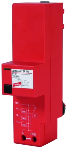
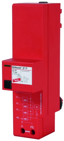
DEHNventil® ZP

Multipole Combined Lightning Current and Surge Arrester for Primary Power Systems

For protecting low-voltage consumer's installations against surges and even direct lightning strikes. For installation in conformity with the lightning protection zone concept at the boundaries from 0A– 2.
  • Type 1 and type 2 combined lightning current and surge arrester with RADAX Flow spark gap technology
  • Fully compliant with all requirements of the national VDN* guideline on the use of SPDs upstream of the meter panel
  • Quick and easy installation by snapping the arrester onto 40 mm busbar systems
  • Test for correct operation by pressing the button with indicator light
  • No tripping of 32 A gG fuses up to short-circuit currents of 25 kArms
  • Discharge capacity up to 100 kA (10/350 µs)
  • Capable of protecting terminal equipment
  • Maximum system availability

Version

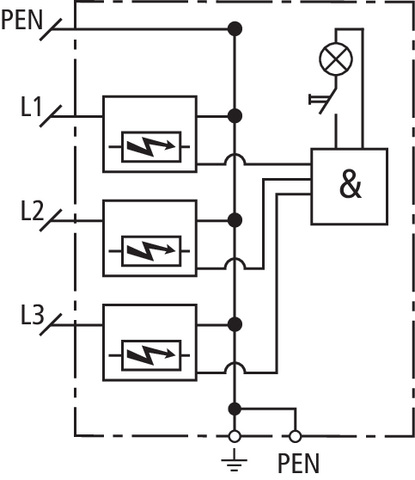
DEHNventil ZP TNC 255: Three-pole combined lightning current and surge arrester for TN-C systems for use in primary power systems in case of buildings with external lightning protection system and high performance parameters
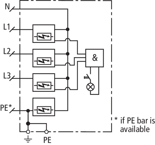
DEHNventil ZP TT 255: Four-pole combined lightning current and surge arrester for TT and TN-S systems for use in primary power systems in case of buildings with external lightning protection system and high performance parameters

Details

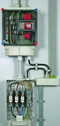
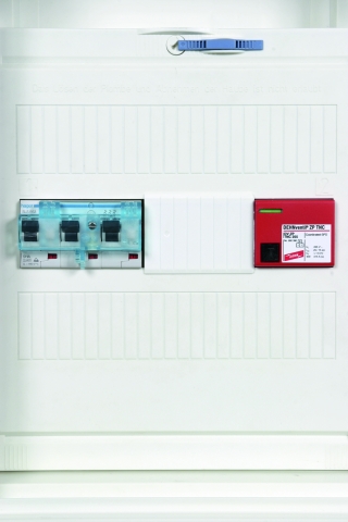
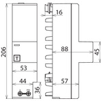
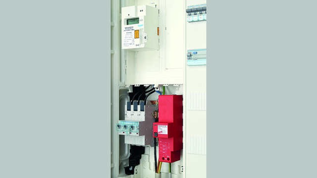
DEHNventil ZP combined lightning current and surge arresters are specifically designed for installation in the busbar connection panels of meter panels. They can be directly snapped onto the busbar system without tools. Their compact dimensions leave enough space for the connecting cable from the service entrance box, even if two selective main circuit breakers are installed.
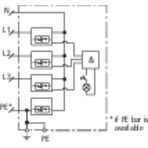
The operating state of the arresters is indicated by an indicator light at the push of a button. Both due to this kind of operating state indication and their design as a spark-gap-based arrester, DEHNventil ZP arresters have no leakage and operating currents.
The RADAX Flow spark gap technology ensures that fuses are not tripped by follow currents even in case of low-current-rated fuses in the service entrance box. Undesirable supply interruptions due to tripped main fuses are thus avoided.
The device parameters and design are fully compliant with all requirements of the German VDN guideline* on the use of surge protective devices in primary power systems.

* VDN ... Verband der Netzbetreiber VDN e. V. beim BDEW
[Association of German Network Operators VDN e. V. at the BDEW in Germany]

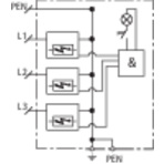
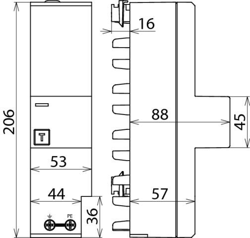
Figure 1 and Figure 2

Models

DEHNventil ZP TNC

DEHNventil ZP TT

DEHNventil ZP TNC

Basic circuit diagram DV ZP TNC 255Dimension drawing DV ZP TNC 255

Combined lightning current and surge arrester for TN-C systems for use in primary power systems in case of buildings with external lightning protection system and high performance parameters (3+0 configuration).


Specifications

Type
Part No.
SPD according to EN 61643-11 / IEC 61643-11
Energy coordination with terminal equipment (≤ 10 m)
Nominal voltage (a.c.) (UN)
Max. continuous operating voltage (a.c.) (UC)
Lightning impulse current (10/350 µs) [L1+L2+L3-PEN] (Itotal)
Specific energy [L1+L2+L3-PEN] (W/R)
Lightning impulse current (10/350 µs) [L-PEN] (Iimp)
Specific energy [L-PEN] (W/R)
Nominal discharge current (8/20 µs) [L-PEN]/[L1+L2+L3-PEN] (In)
Voltage protection level (UP)
Follow current extinguishing capability (a.c.) (Ifi)
Follow current limitation / Selectivity
Response time (tA)
Max. backup fuse up to IK = 25 kArms
Max. backup fuse for IK > 25 kArms
Temporary overvoltage (TOV) [L-PEN] (UT) – Characteristic
Operating temperature range (TU)
Operating state indication
Number of ports
Cross-sectional area (PEN, 9)
For mounting on
Enclosure material
Place of installation
Degree of protection
Capacity
Approvals
Weight
GTIN
PU
Part No.
  • DV ZP TNC 255
  • 900 390
  • type 1 + type 2 / class I + class II
  • type 1 + type 2 + type 3
  • 230 / 400 V (50 / 60 Hz)
  • 255 V (50 / 60 Hz)
  • 75 kA
  • 1.40  MJ/ohms
  • 25 kA
  • 156.25 kJ/ohms
  • 25 / 75 kA
  • ≤ 1.5 kV
  • 25 kArms
  • no tripping of a 32 A gG fuse up to 25 kArms (prosp.)
  • ≤ 100 ns
  • 315 A gG
  • 200 A gG
  • 440 V / 120 min. – withstand
  • -40 °C ... +80 °C
  • button with indicator light
  • 1
  • 10-35 mm2 flexible / 50 mm2 stranded
  • 40 mm busbar systems
  • thermoplastic, red, UL 94 V-0
  • indoor installation
  • IP 30 (in combination with cover)
  • 3 module(s), DIN 43880
  • VDE
  • 914 g
  • 4013364105751
  • 1 pc(s)
  • 900 390
  • Specifications (PDF)
  • More
    • Further Pictures
      Basic circuit diagram DV ZP TNC 255
      open PDF
      Dimension drawing DV ZP TNC 255
      open PDF
      Further Information
      Product Specifications (Text)

      Back

      DEHNventil ZP TNC 255 combined arrester
      Three-pole combined arrester for use in 230/400 V TN-C systems
      For use upstream of the meter according to national regulations 
      (e.g. Germany: VDN directive)
      Type 1 + Type 2 SPD according to EN 61643-11
      RADAX-Flow spark gap technology
      for follow current limitation
      Can be directly snapped onto 40 mm busbar systems 
      without tools in the lower  compartment of the meter panel 
      Max. continuous operating voltage: 255 V a.c.
      Voltage protection level:  <= 1.5 kV
      Lightning impulse current (10/350 µs): 75 kA
      Follow current extinguishing capability: 25 kArms
      Energy-coordinated according to IEC 62305-4 with 
      arresters of the Red/Line series and terminal equipment
      Operating state indication 

      delivery and installation.

      Brand: DEHN
      Type: DV ZP TNC 255
      Part No.: 900 390

      or equivalent.
      Installation Instructions
      Certificates
      CE_DV_ZP_TNC_255
      Bestaetigung DV ZP Vorzaehlerbereich
      40012453
      CAD-Data for registered Users
      900390.stp
      900390.igs
      900390.jt
      900390.dwg
      900390m_D.dxf

DEHNventil ZP TT

Basic circuit diagram DV ZP TT 255Dimension drawing DV ZP TT 255

Combined lightning current and surge arrester for TT and TN-S systems for use in primary power systems in case of buildings with external lightning protection system and high performance parameters (3+1 configuration).


Specifications

Type
Part No.
SPD according to EN 61643-11 / IEC 61643-11
Energy coordination with terminal equipment (≤ 10 m)
Nominal voltage (a.c.) (UN)
Max. continuous operating voltage (a.c.) (UC)
Lightning impulse current (10/350 µs) [L1+L2+L3+N-PE] (Itotal)
Specific energy [L1+L2+L3+N-PE] (W/R)
Lightning impulse current (10/350 µs) [L-N] (Iimp)
Specific energy [L-N] (W/R)
Lightning impulse current (10/350 µs) [N-PE] (Iimp)
Specific energy [N-PE] (W/R)
Nominal discharge current (8/20 µs) [L-N]/[N-PE] (In)
Voltage protection level [L-N] (UP)
Voltage protection level [N-PE] (UP)
Follow current extinguishing capability [L-N] (a.c.) (Ifi)
Follow current extinguishing capability [N-PE] (a.c.) (Ifi)
Follow current limitation / Selectivity
Response time (tA)
Max. backup fuse up to IK = 25 kArms
Max. backup fuse for IK > 25 kArms
Temporary overvoltage (TOV) [L-N] (UT) – Characteristic
Temporary overvoltage (TOV) [N-PE] (UT) – Characteristic
Operating temperature range (TU)
Operating state indication
Number of ports
Cross-sectional area (PE, 9)
For mounting on
Enclosure material
Place of installation
Degree of protection
Capacity
Approvals
Extended technical data:
Voltage protection level [L-PE] (UP)
Weight
GTIN
PU
Part No.
  • DV ZP TT 255
  • 900 391
  • type 1 + type 2 / class I + class II
  • type 1 + type 2 + type 3
  • 230 / 400 V (50 / 60 Hz)
  • 255 V (50 / 60 Hz)
  • 100 kA
  • 2.50 MJ/ohms
  • 25 kA
  • 156.25 kJ/ohms
  • 100 kA
  • 2.50  MJ/ohms
  • 25 / 100 kA
  • ≤ 1.5 kV
  • ≤ 1.5 kV
  • 25 kArms
  • 100 Arms
  • no tripping of a 32 A gG fuse up to 25 kArms (prosp.)
  • ≤ 100 ns
  • 315 A gG
  • 200 A gG
  • 440 V / 120 min. – withstand
  • 1200 V / 200 ms – withstand
  • -40 °C ... +80 °C
  • button with indicator light
  • 1
  • 10-35 mm2 flexible / 50 mm2 stranded
  • 40 mm busbar systems
  • thermoplastic, red, UL 94 V-0
  • indoor installation
  • IP 30 (in combination with cover)
  • 3 module(s), DIN 43880
  • VDE
  • ---------------------------------
  • 2.2 kV
  • 1,01 kg
  • 4013364105768
  • 1 pc(s)
  • 900 391
  • Specifications (PDF)
  • More
    • Further Pictures
      Basic circuit diagram DV ZP TT 255
      open PDF
      Dimension drawing DV ZP TT 255
      open PDF
      Further Information
      Product Specifications (Text)

      Back

      DEHNventil ZP TT 255 combined arrester
      Four-pole combined arrester for 230/400 V 
      TT and TN(C)-S systems
      For use upstream of the meter according to national regulations 
      (e.g. Germany: VDN directive)
      Type 1 + Type 2 SPD acc. to EN 61643-11
      RADAX-Flow spark gap technology
      for follow current limitation
      Can be directly snapped onto 40 mm busbar systems 
      without tools in the lower compartment of the meter panel 
      Max. continuous operating voltage: 255 V a.c.
      Voltage protection level: <= 1.5 kV
      Lightning impulse current  (10/350 µs): 100 kA
      Follow current extinguishing capability: 25 kArms
      Energy-coordinated according to IEC 62305-4 with 
      arresters of the Red/Line series and terminal equipment 
      Fault indication

      delivery and installation.

      Brand: DEHN
      Type: DV ZP TT 255
      Part No.: 900 391

      or equivalent.
      Installation Instructions
      Certificates
      40012453
      Bestaetigung DV ZP Vorzaehlerbereich
      CE_DV_ZP_TT_255
      CAD-Data for registered Users
      900391.stp
      900391.igs
      900391.jt
      900391.dwg
      900391m_D.dxf