DEHNprotector

Surge Arrester

Combined surge protective adapter with visual operating state and fault indication plugged into an earthed socket outlet.
  • Combined surge protection for the power and data side of terminal equipment
  • Protection of
  • – TVs and satellite devices – ISDN and telephone systems – Ethernet components
  • Visual operating state / fault indication
  • Easy retrofitting

Description

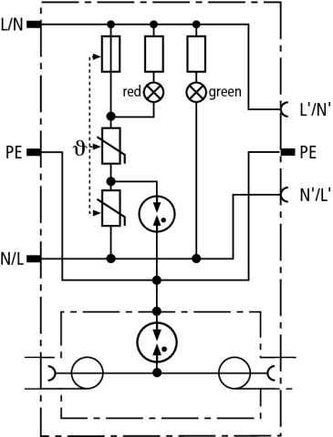
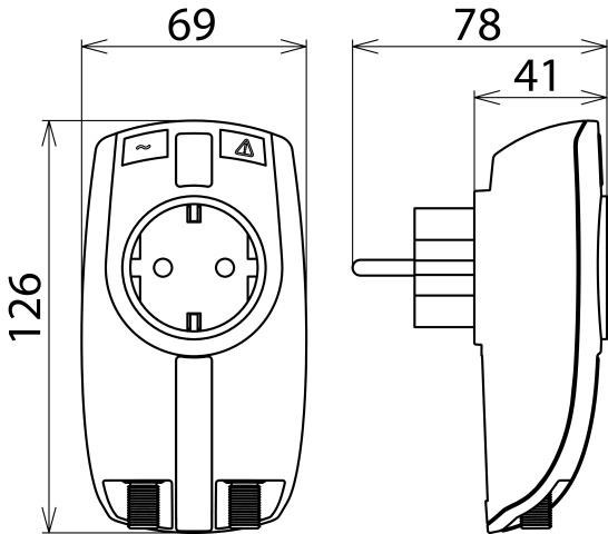
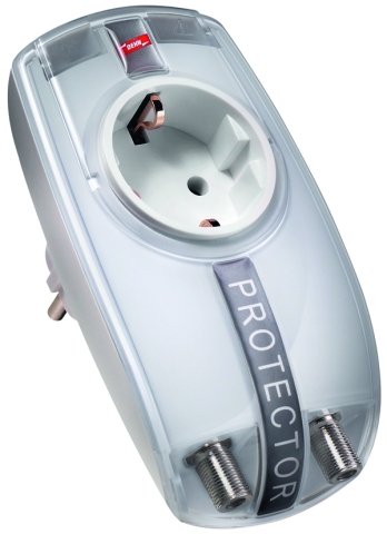
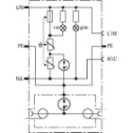
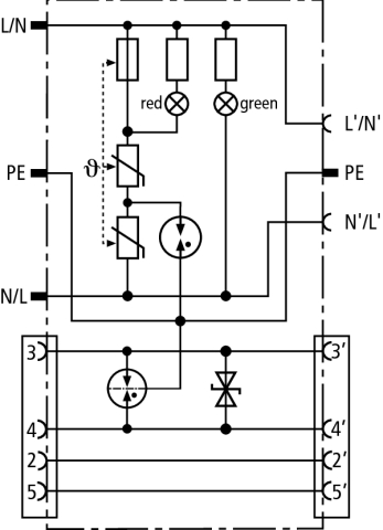
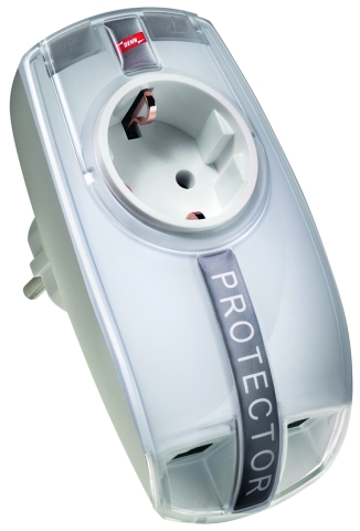
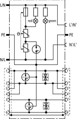
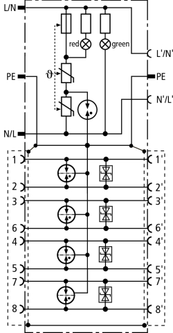
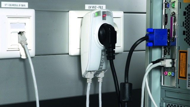
The arresters of the DEHNprotector family are plugged into earthed socket outlets and protect terminal equipment with an additional data interface. Surges are discharged to the PE contact of the socket outlet. The plug-in installation facilitates retrofitting of surge protection. The surge protective device for the power side features a visual operating state and fault indication, thus ensuring easy maintenance.
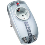
Detail 1

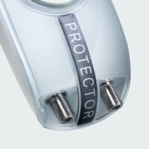
Type with coaxial connection.
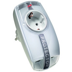
Detail 2

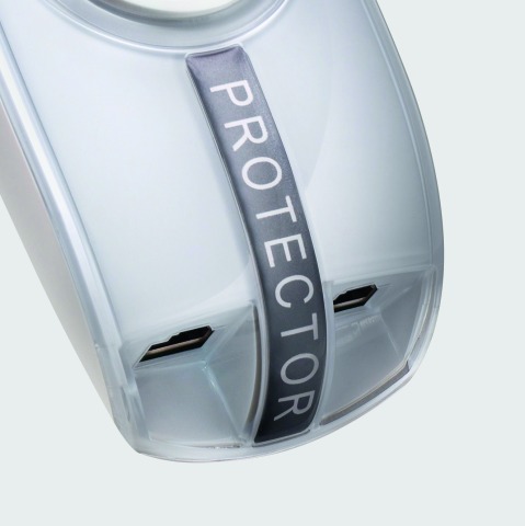
Type with RJ connection.
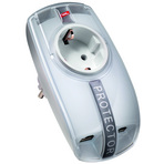
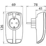
Detail 3

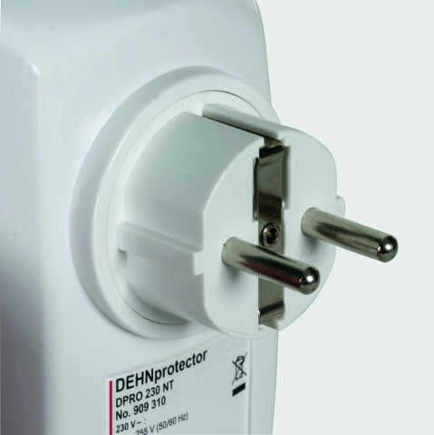
Plug for earthed socket outlets for protecting the power side.

Detail 4

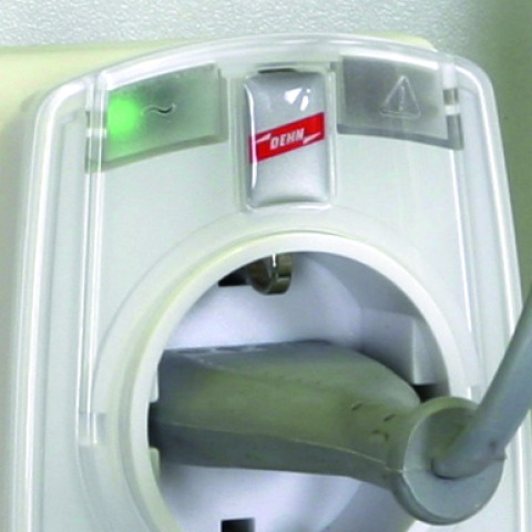
Visual operating state and fault indication of the power side (230 V).

Models

DPRO 230 TV

DPRO 230 NT

DPRO 230 ISDN

DPRO 230 LAN100

DPRO 230 TV

Basic circuit diagram DPRO TVDimension drawing DPRO TV

Combined surge protection for the power and antenna side of TV, radio or satellite receivers. With visual operating state and fault indication and integrated child lock.


Specifications

Type
Part No.
Protection of the data side
SPD class
Max. continuous operating voltage (d.c.) (UC)
C2 Nominal discharge current (8/20 µs) line-shield (PE) (In)
Voltage protection level line-shield (PE) at 1 kV/µs C3 (Up)
Insertion loss 0-2400 MHz
Operating temperature range (TU)
Degree of protection
Connection (input / output)
Earthing via
Enclosure material
Colour
Test standards
Protection of the power side
SPD according to EN 61643-11 / IEC 61643-11
Nominal voltage (a.c.) (UN)
Max. continuous operating voltage (a.c.) (UC)
Nominal load current (a.c.) (IL)
Nominal discharge current (8/20 µs) (In)
Total discharge current (8/20 µs) [L+N-PE] (Itotal)
Combination wave (Uoc)
Combination wave [L+N-PE] (Uoc total)
Voltage protection level [L-N] (Up)
Voltage protection level [L/N-PE] (Up)
Response time [L-N] (tA)
Response time [L/N-PE] (tA)
Max. mains-side overcurrent protection
Short-circuit withstand capability for mains-side overcurrent protection (ISCCR)
Temporary overvoltage (TOV) [L-N] (UT) – Characteristic
Temporary overvoltage (TOV) [L/N-PE] (UT) – Characteristic
Temporary overvoltage (TOV) [L+N-PE] (UT) – Characteristic
Fault indication
Operating state indication
Number of ports
For mounting on
Test standards
Weight
GTIN
PU
Part No.
  • DPRO 230 TV
  • 909 300
  •  
  • B
  • 60 V
  • 5 kA
  • ≤ 600 V
  • ≤ 1.5 dB
  • -25 °C ... +40 °C
  • IP 20
  • F socket / F socket
  • protective conductor connection
  • thermoplastic, UL 94 V-2
  • pure white
  • IEC 61643-21 / EN 61643-21
  •  
  • type 3 / class III
  • 230 V (50 / 60 Hz)
  • 255 V (50 / 60 Hz)
  • 16 A
  • 3 kA
  • 5 kA
  • 6 kV
  • 10 kV
  • ≤ 1.25 kV
  • ≤ 1.5 kV
  • ≤ 25 ns
  • ≤ 100 ns
  • 16 A gL/gG or B 16 A
  • 1 kArms
  • 335 V / 5 sec. – withstand
  • 440 V / 120 min. – safe failure
  • 335 V / 120 min. – withstand
  • 440 V / 5 sec. – withstand
  • 1200 V + UREF / 200 ms – safe failure
  • red indicator light
  • green indicator light
  • 1
  • earthed socket outlets DIN 49440 / DIN 49441
  • EN 61643-11
  • 234 g
  • 4013364117723
  • 1 pc(s)
  • 909 300
  • Specifications (PDF)
  • More
    • Further Pictures
      Basic circuit diagram DPRO 230 TV
      open PDF
      Dimension drawing DPRO 230 TV
      open PDF
      Further Information
      Product Specifications (Text)

      Back

      DEHNprotector DPRO 230 TV combined surge protection
      Surge protective adapter
      with combined protection for the power
      and antenna side of television receivers, 
      radios and video players including adapter
      from F sockets to IEC connections
      Tested to EN61643-11 and -21
      Protective circuit with integrated monitoring device
      and visual operating state and fault indication
      Power side: Type 3
      Data side: Type 2
      Connection (input / output): F socket / F socket 

      delivery and installation.

      Brand: DEHN
      Type: DPRO 230 TV
      Part No.: 909 300

      or equivalent.
      Installation Instructions
      Certificates
      CE_DPRO_230_TV
      CAD-Data for registered Users
      909300m_D.dxf

DPRO 230 NT

Basic circuit diagram DPRO NTDimension drawing DPRO NT

Combined surge protection for the power and data side of a digital network termination (NT). Also suited for telephones and fax machines. With visual operating state and fault indication and integrated child lock.


Specifications

Type
Part No.
Protection of the data side
SPD class
Max. continuous operating voltage (d.c.) (UC)
Lightning impulse current (10/350 µs) per line D1 (Iimp)
C2 Nominal discharge current (8/20 µs) per line (In)
Voltage protection level line-line for In C2 (Up)
Voltage protection level line-PE for In C2 (Up)
Voltage protection level line-line at 1 kV/µs C3 (Up)
Voltage protection level line-PE at 1 kV/µs C3 (Up)
Cut-off frequency (fG)
Operating temperature range (TU)
Degree of protection
Connection (input / output)
Pinning
Earthing via
Enclosure material
Colour
Test standards
Protection of the power side
SPD according to EN 61643-11 / IEC 61643-11
Nominal voltage (a.c.) (UN)
Max. continuous operating voltage (a.c.) (UC)
Nominal load current (a.c.) (IL)
Nominal discharge current (8/20 µs) (In)
Total discharge current (8/20 µs) [L+N-PE] (Itotal)
Combination wave (Uoc)
Combination wave [L+N-PE] (Uoc total)
Voltage protection level [L-N] (Up)
Voltage protection level [L/N-PE] (Up)
Response time [L-N] (tA)
Response time [L/N-PE] (tA)
Max. mains-side overcurrent protection
Short-circuit withstand capability for mains-side overcurrent protection (ISCCR)
Temporary overvoltage (TOV) [L-N] (UT) – Characteristic
Temporary overvoltage (TOV) [L/N-PE] (UT) – Characteristic
Temporary overvoltage (TOV) [L+N-PE] (UT) – Characteristic
Fault indication
Operating state indication
Number of ports
For mounting on
Test standards
Weight
GTIN
PU
Part No.
  • DPRO 230 NT
  • 909 310
  •  
  • Q
  • 180 V
  • 1 kA
  • 2.5 kA
  • ≤ 300 V
  • ≤ 500 V
  • ≤ 300 V
  • ≤ 500 V
  • 50 MHz
  • -25 °C ... +40 °C
  • IP 20
  • RJ12 socket / RJ12 socket
  • 3/4
  • protective conductor connection
  • thermoplastic, UL 94 V-2
  • pure white
  • IEC 61643-21 / EN 61643-21
  •  
  • type 3 / class III
  • 230 V (50 / 60 Hz)
  • 255 V (50 / 60 Hz)
  • 16 A
  • 3 kA
  • 5 kA
  • 6 kV
  • 10 kV
  • ≤ 1.25 kV
  • ≤ 1.5 kV
  • ≤ 25 ns
  • ≤ 100 ns
  • B 16 A
  • 1 kArms
  • 335 V / 5 sec. – withstand
  • 440 V / 120 min. – safe failure
  • 335 V / 120 min. – withstand
  • 440 V / 5 sec. – withstand
  • 1200 V + UREF / 200 ms – safe failure
  • red indicator light
  • green indicator light
  • 1
  • earthed socket outlets DIN 49440 / DIN 49441
  • EN 61643-11
  • 212 g
  • 4013364117747
  • 1 pc(s)
  • 909 310
  • Specifications (PDF)
  • More
    • Further Pictures
      Basic circuit diagram DPRO 230 NT
      open PDF
      Dimension drawing DPRO 230 NT
      open PDF
      Further Information
      Product Specifications (Text)

      Back

      DEHNprotector DPRO 230 NT combined surge protection
      Surge protective adapter
      with combined protection for the power
      and data Uk0 of a digital network termination NT,
      as well as for telephones and fax devices
      including accessories for RJ11/12
      and TAE connection
      Tested to EN61643-11 and -21
      Protective circuit with integrated monitoring device
      and visual operating state and fault indication
      Power side: Type 3
      Data side: Type 2/P2
      Connection (input / output): RJ12 socket / RJ12 socket 
      Pinning: 3/4 

      delivery and installation.

      Brand: DEHN
      Type: DPRO 230 NT
      Part No.: 909 310

      or equivalent.
      Installation Instructions
      Certificates
      CE_DPRO_230_NT
      CAD-Data for registered Users
      909310m_D.dxf

DPRO 230 ISDN

Basic circuit diagram DPRO ISDNDimension drawing DPRO ISDN

Combined surge protection for the power and ISDN S0 side of ISDN systems and devices. Shielded port allows to protect Ethernet 10 BT. With visual operating state and fault indication and integrated child lock.


Specifications

Type
Part No.
Protection of the data side
SPD class
Max. continuous operating voltage (d.c.) (UC)
Lightning impulse current (10/350 µs) per line D1 (Iimp)
C2 Nominal discharge current (8/20 µs) line-line (In)
C2 Nominal discharge current (8/20 µs) line-PE (In)
C2 Total nominal discharge current (8/20 µs) (In)
Voltage protection level line-line for In C2 (Up)
Voltage protection level line-PE for In C2 (Up)
Voltage protection level line-line at 1 kV/µs C3 (Up)
Voltage protection level line-PE at 1 kV/µs C3 (Up)
Cut-off frequency (fG)
Operating temperature range (TU)
Degree of protection
Connection (input / output)
Pinning
Earthing via
Enclosure material
Colour
Test standards
Protection of the power side
SPD according to EN 61643-11 / IEC 61643-11
Nominal voltage (a.c.) (UN)
Max. continuous operating voltage (a.c.) (UC)
Nominal load current (a.c.) (IL)
Nominal discharge current (8/20 µs) (In)
Total discharge current (8/20 µs) [L+N-PE] (Itotal)
Combination wave (Uoc)
Combination wave [L+N-PE] (Uoc total)
Voltage protection level [L-N] (Up)
Voltage protection level [L/N-PE] (Up)
Response time [L-N] (tA)
Response time [L/N-PE] (tA)
Max. mains-side overcurrent protection
Short-circuit withstand capability for mains-side overcurrent protection (ISCCR)
Temporary overvoltage (TOV) [L-N] (UT) – Characteristic
Temporary overvoltage (TOV) [L/N-PE] (UT) – Characteristic
Temporary overvoltage (TOV) [L+N-PE] (UT) – Characteristic
Fault indication
Operating state indication
Number of ports
For mounting on
Test standards
Weight
GTIN
PU
Part No.
  • DPRO 230 ISDN
  • 909 320
  •  
  • Q
  • 48 V
  • 1 kA
  • 120 A
  • 2.5 kA
  • 10 kA
  • ≤ 100 V
  • ≤ 500 V
  • ≤ 80 V
  • ≤ 500 V
  • 50 MHz
  • -25 °C ... +40 °C
  • IP 20
  • shielded RJ45 socket / shielded RJ45 socket
  • 1(5)/2(4), 3/6
  • protective conductor connection
  • thermoplastic, UL 94 V-2
  • pure white
  • IEC 61643-21 / EN 61643-21
  •  
  • type 3 / class III
  • 230 V (50 / 60 Hz)
  • 255 V (50 / 60 Hz)
  • 16 A
  • 3 kA
  • 5 kA
  • 6 kV
  • 10 kV
  • ≤ 1.25 kV
  • ≤ 1.5 kV
  • ≤ 25 ns
  • ≤ 100 ns
  • B 16 A
  • 1 kArms
  • 335 V / 5 sec. – withstand
  • 440 V / 120 min. – safe failure
  • 335 V / 120 min. – withstand
  • 440 V / 5 sec. – withstand
  • 1200 V + UREF / 200 ms – safe failure
  • red indicator light
  • green indicator light
  • 1
  • earthed socket outlets DIN 49440 / DIN 49441
  • EN 61643-11
  • 215 g
  • 4013364136885
  • 1 pc(s)
  • 909 320
  • Specifications (PDF)
  • More
    • Further Pictures
      Basic circuit diagram DPRO 230 ISDN
      open PDF
      Dimension drawing DPRO 230 ISDN
      open PDF
      Further Information
      Product Specifications (Text)

      Back

      DEHNprotector DPRO 230 ISDN combined surge protection
      Surge protective adapter
      with combined protection for the power
      and ISDN (S0) side of ISDN systems and devices,
      incl. 1.5 m long shielded patch cable
      Tested to EN61643-11 and -21
      Protective circuit with integrated monitoring device
      and visual operating state and fault indication
      Power side: Type 3
      Data side: Type 2/P1
      Connection (input / output): shielded RJ45 socket / shielded RJ45 socket 
      Pinning: 1(5)/2(4), 3/6 

      delivery and installation.

      Brand: DEHN
      Type: DPRO 230 ISDN
      Part No.: 909 320

      or equivalent.
      Installation Instructions
      Certificates
      CE_DPRO_230_ISDN
      CAD-Data for registered Users
      909310m_D.dxf

DPRO 230 LAN100

Basic circuit diagram DPRO LAN100Dimension drawing DPRO LAN100

Combined surge protection for the power side and data input for protecting LAN components. Protection of all pairs for Ethernet pin assignment.
It meets the requirements for channel class D in accordance with EN 50173 and is thus suitable for 1000 Base-T (Gigabit Ethernet).
With visual operating state and fault indication and integrated child lock.


Specifications

Type
Part No.
Protection of the data side
SPD class
Max. continuous operating voltage (d.c.) (UC)
Lightning impulse current (10/350 µs) per line D1 (Iimp)
C2 Nominal discharge current (8/20 µs) line-line (In)
C2 Nominal discharge current (8/20 µs) line-PE (In)
C2 Total nominal discharge current (8/20 µs) (In)
Voltage protection level line-line for In C2 (Up)
Voltage protection level line-PE for In C2 (Up)
Voltage protection level line-line at 1 kV/µs C3 (Up)
Voltage protection level line-PE at 1 kV/µs C3 (Up)
Cut-off frequency (fG)
Operating temperature range (TU)
Degree of protection
Connection (input / output)
Pinning
Earthing via
Enclosure material
Colour
Test standards
Protection of the power side
SPD according to EN 61643-11 / IEC 61643-11
Nominal voltage (a.c.) (UN)
Max. continuous operating voltage (a.c.) (UC)
Nominal load current (a.c.) (IL)
Nominal discharge current (8/20 µs) (In)
Total discharge current (8/20 µs) [L+N-PE] (Itotal)
Combination wave (Uoc)
Combination wave [L+N-PE] (Uoc total)
Voltage protection level [L-N] (Up)
Voltage protection level [L/N-PE] (Up)
Response time [L-N] (tA)
Response time [L/N-PE] (tA)
Max. mains-side overcurrent protection
Short-circuit withstand capability for mains-side overcurrent protection (ISCCR)
Temporary overvoltage (TOV) [L-N] (UT) – Characteristic
Temporary overvoltage (TOV) [L/N-PE] (UT) – Characteristic
Temporary overvoltage (TOV) [L+N-PE] (UT) – Characteristic
Fault indication
Operating state indication
Number of ports
For mounting on
Test standards
Weight
GTIN
PU
Part No.
  • DPRO 230 LAN100
  • 909 321
  •  
  • Q
  • 58 V
  • 1 kA
  • 30 A
  • 2.5 kA
  • 10 kA
  • ≤ 100 V
  • ≤ 500 V
  • 90 V
  • ≤ 500 V
  • 120 MHz
  • -25 °C ... +40 °C
  • IP 20
  • shielded RJ45 socket / shielded RJ45 socket
  • 1/2, 3/6, 4/5, 7/8
  • protective conductor connection
  • thermoplastic, UL 94 V-2
  • pure white
  • IEC 61643-21 / EN 61643-21
  •  
  • type 3 / class III
  • 230 V (50 / 60 Hz)
  • 255 V (50 / 60 Hz)
  • 16 A
  • 3 kA
  • 5 kA
  • 6 kV
  • 10 kV
  • ≤ 1.25 kV
  • ≤ 1.5 kV
  • ≤ 25 ns
  • ≤ 100 ns
  • B 16 A
  • 1 kArms
  • 335 V / 5 sec. – withstand
  • 440 V / 120 min. – safe failure
  • 335 V / 120 min. – withstand
  • 440 V / 5 sec. – withstand
  • 1200 V + UREF / 200 ms – safe failure
  • red indicator light
  • green indicator light
  • 1
  • earthed socket outlets DIN 49440 / DIN 49441
  • EN 61643-11
  • 222 g
  • 4013364126152
  • 1 pc(s)
  • 909 321
  • Specifications (PDF)
  • More
    • Further Pictures
      Basic circuit diagram DPRO 230 LAN100
      open PDF
      Dimension drawing DPRO 230 LAN100
      open PDF
      Further Information
      Product Specifications (Text)

      Back

      DEHNprotector DPRO 230 LAN100 combined surge protective device
      Surge protection adapter
      with combined protection for the power
      side and data input of LAN components in Ethernet 
      100BaseT; 1.5m shielded patch cable included.
      Tested in accordance with EN61643-11 and -21.
      Protective circuit with integrated monitoring device
      and visual operating state and fault indication.
      Power side: Type 3
      Data side: Type 2/P1
      Connection (input / output): shielded RJ45 socket / shielded RJ45 socket 
      Pinning: 1/2, 3/6, 4/5, 7/8 

      delivery and installation.

      Brand: DEHN
      Type: DPRO 230 LAN100
      Part No.: 909 321

      or equivalent.
      Installation Instructions
      Certificates
      CE_DPRO_230_LAN100
      CAD-Data for registered Users
      909310m_D.dxf