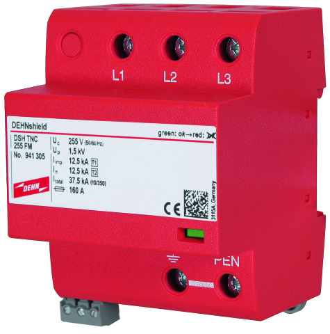
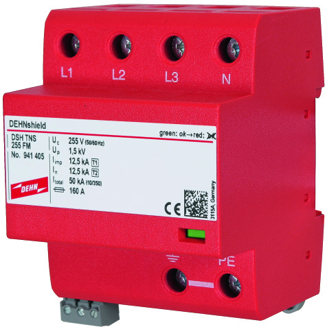
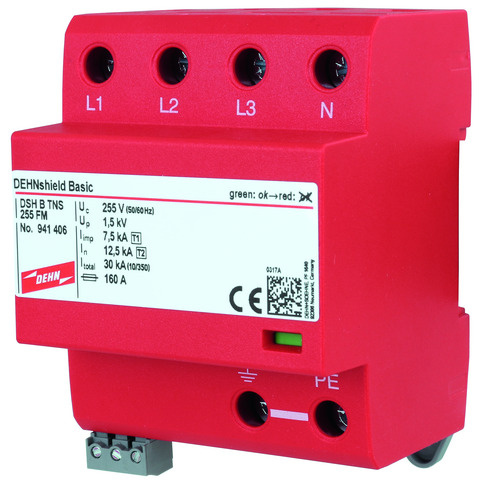
DEHNshield®

Application-optimised multipole Combined Lightning Current and Surge Arrester

For protecting compact low-voltage consumer's installations against surges and even direct lightning strikes. For installation in conformity with the lightning protection zone concept at the boundaries from 0A– 2.
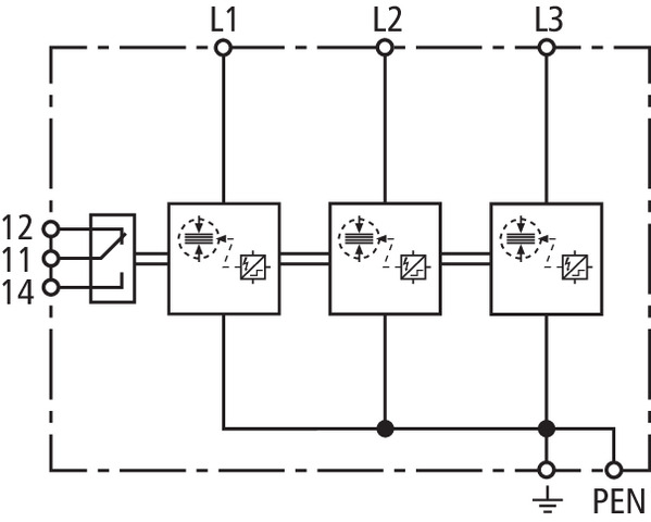
  • Application-optimised and prewired spark-gap-based type 1 and type 2 combined lightning current and surge arrester
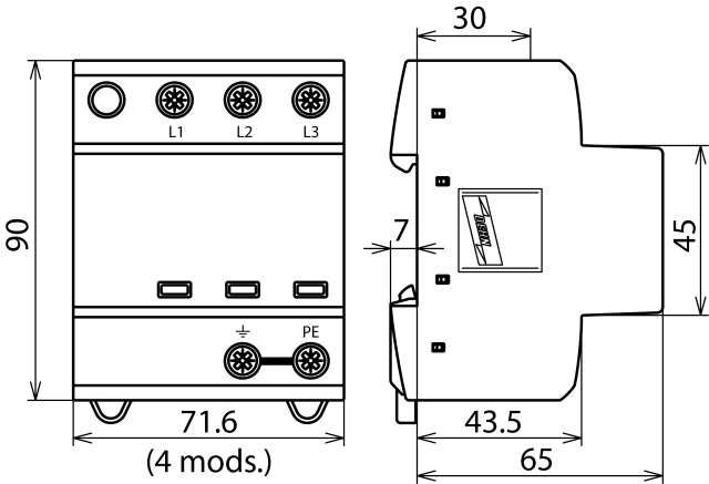
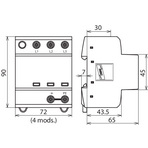
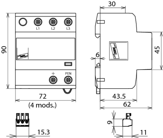
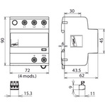
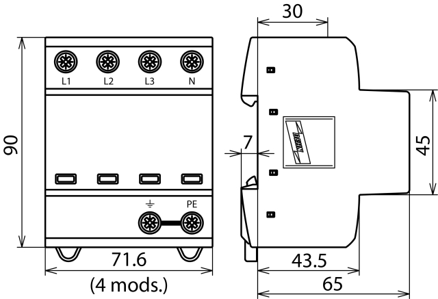
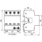
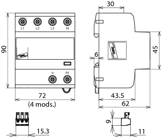
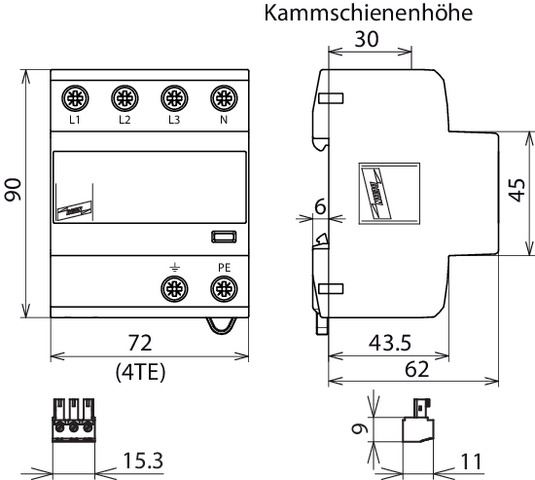
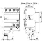
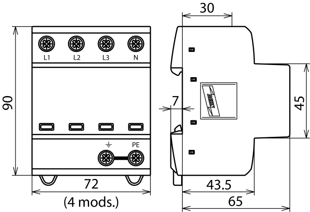
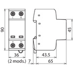
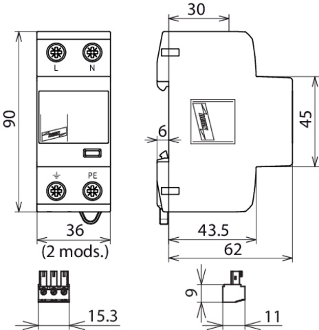
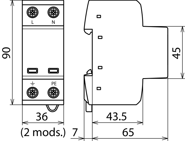
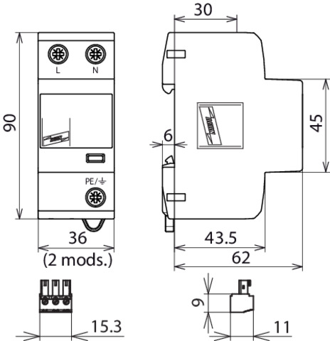
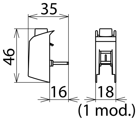
  • Compact design due to space-saving spark gap technology with a width of only 1 module / pole
  • Fulfils the minimum requirements on the lightning current discharge capacity according to IEC 60364-5-53
  • Allows compact lightning equipotential bonding including protection of terminal equipment
  • Discharge capacity up to 50 kA (10/350 µs)
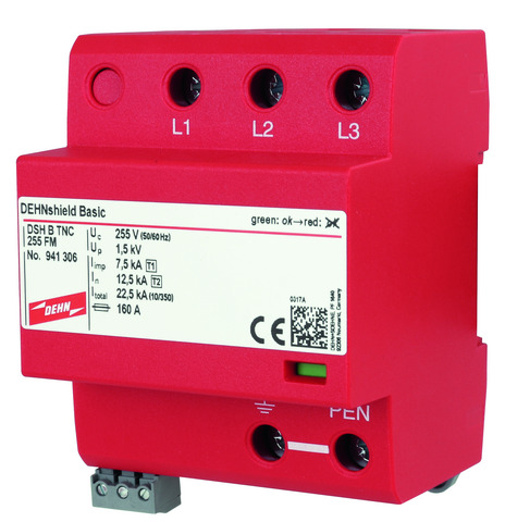
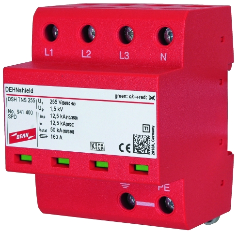
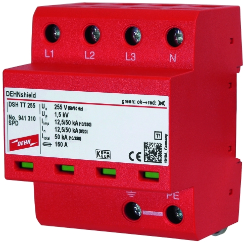
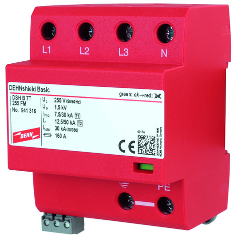
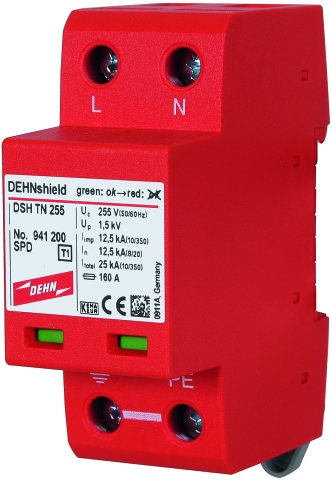
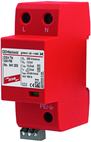
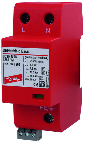
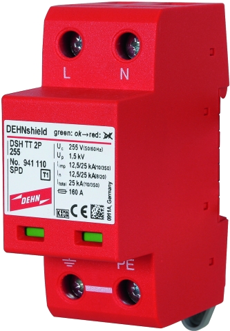
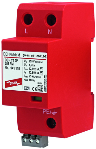
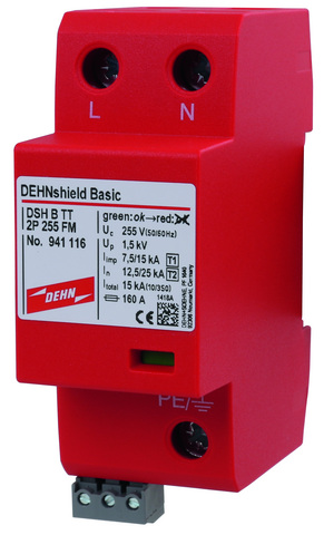
  • Operating state / fault indication by green / red indicator flag in the inspection window
  • High follow current extinguishing capacity (Ifi = 25 kArms)

Version

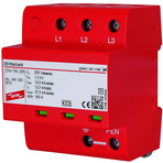
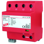
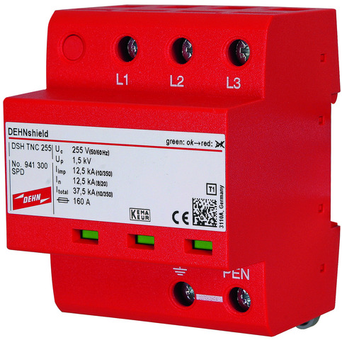
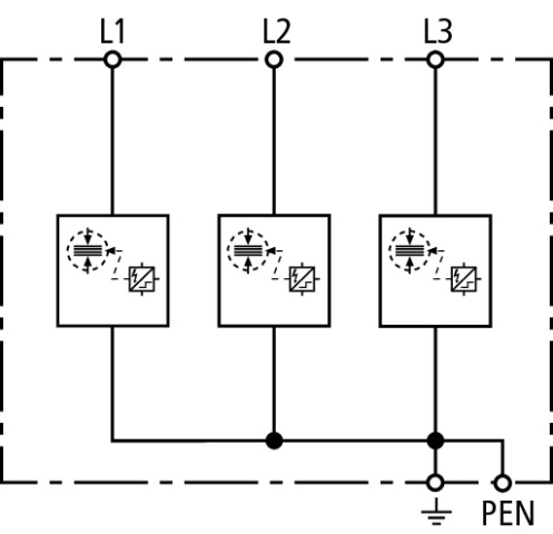
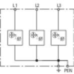
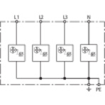
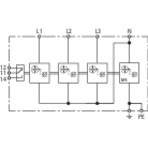
DEHNshield TNC 255: Application-optimised combined lightning current and surge arrester for TN-C systems
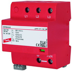
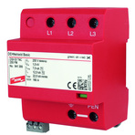
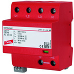
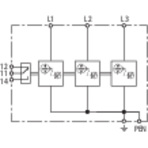
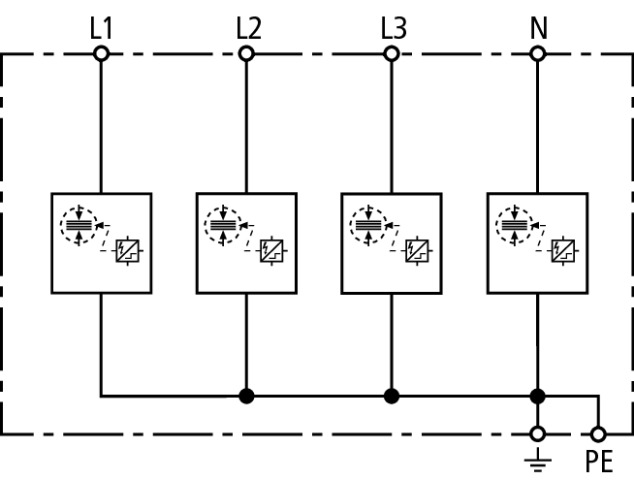
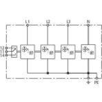
DEHNshield TNS 255: Application-optimised combined lightning current and surge arrester for TN-S systems
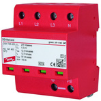
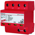
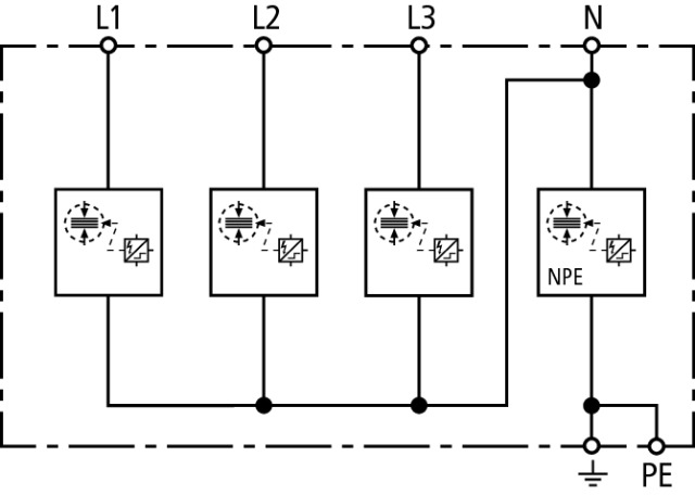
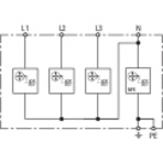
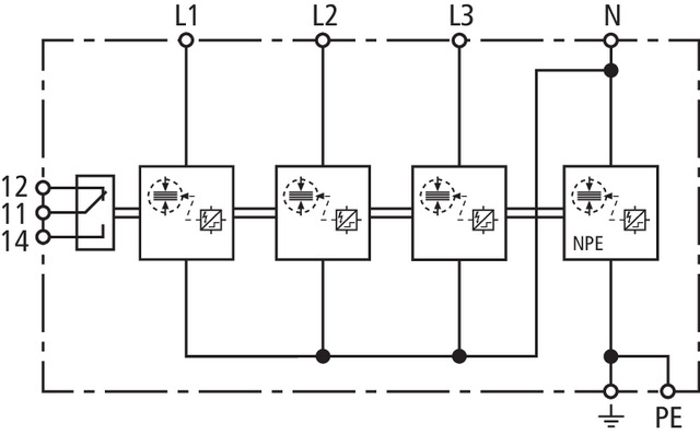
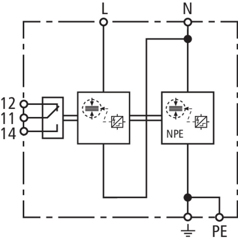
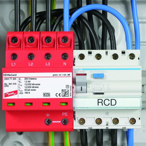
DEHNshield TT 255: Application-optimised combined lightning current and surge arrester for TT and TN-S systems (3+1 configuration)
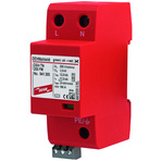
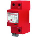
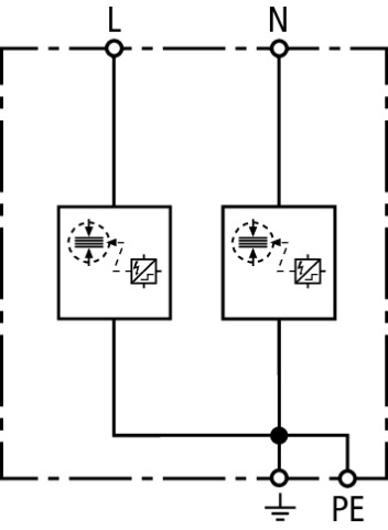
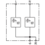
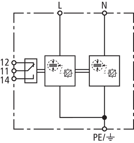
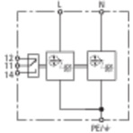
DEHNshield TN 255: Application-optimised combined lightning current and surge arrester for single-phase TN systems
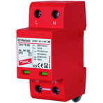
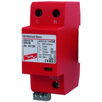
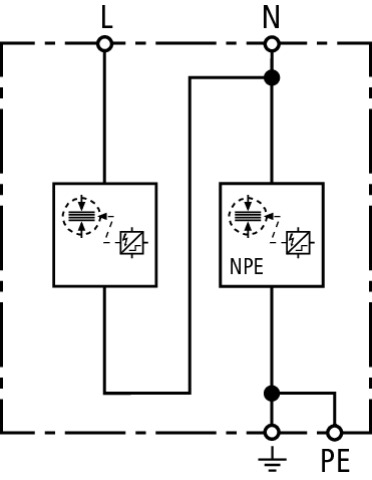
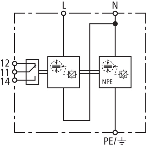
DEHNshield TT 2P 255: Application-optimised combined lightning current and surge arrester for single-phase TT and TN systems (1+1 configuration)
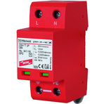
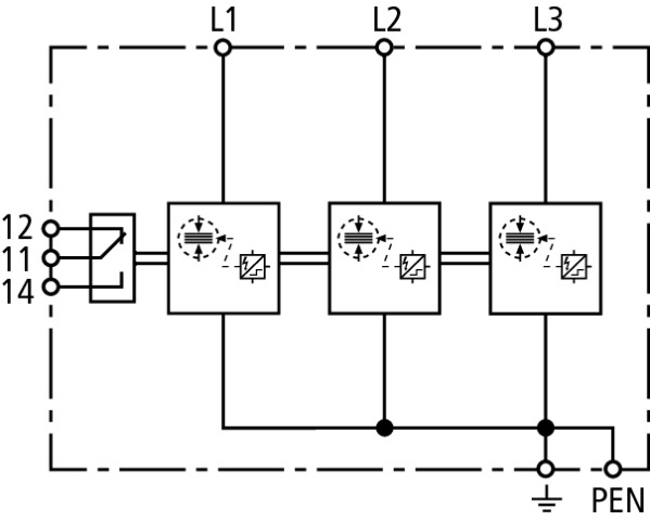
DEHNshield … FM: With remote signalling contact for monitoring device (floating changeover contact)
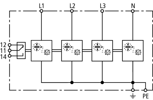
Details

Series connection by means of a lightning-current-tested STAK 25 pin-shaped terminal
The space-saving and application-optimised DEHNshield family offers various benefits provided by type 1 and type 2 spark-gap-based arresters such as the "wave breaker function" (WBF). This function and the associated reduction of the pulse time mitigate the energy of the lightning impulse current to an acceptable level for downstream protection stages or terminal equipment. Moreover, DEHNshield arresters are directly energy coordinated with other arresters of the Red/Line product family.
Application-optimised DEHNshield combined lightning current and surge arresters combine lightning equipotential bonding up to lightning impulse currents of 50 kA (10/350 µs) and surge protection in a single device.
This clearly distinguishes DEHNshield from varistor-based arresters of this application and performance class.

Due to their technical parameters and the very compact design as spark-gap-based arrester with only one module / pole, DEHNshield arresters are ideally suited for this application class. For this reason, they are a space-saving and application-optimised solution in particular for residential buildings.
DEHNshield arresters also provide optimal protection in existing buildings without external lightning protection system where roof superstructures or overhead line supplies are installed which require type 1 SPDs according to VdS 2031.
No additional backup fuse is required if an installation is protected by backup fuses up to 160 A.
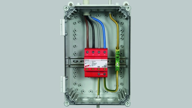
The energy-coordinated arresters even allow to protect terminal equipment if the distance between DEHNshield and the loads is ≤ 10 m. The spark gap without venting means and the small space requirements of the application-optimised combined lightning current and surge arresters enable easy integration into distribution boards.
The follow-current-limiting spark gap technology ensures selectivity with regard to low-current-rated fuses (35 A gG). This means that upstream fuses will not trip due to mains follow currents.

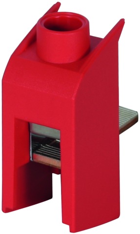
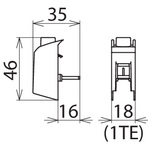
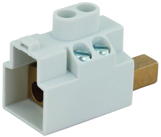
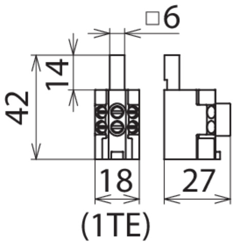
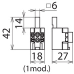
Busbars and pin-shaped terminals from DEHN can be used for connecting DEHNshield to other DIN rail mounted devices. The type designation of DEHNshield allows to easily choose the right arrester for the relevant system configuration of the low-voltage consumer’s installation.
The operating state / fault indicator of every protective path needs no power to operate and instantly shows the operating state of the arrester. Apart from the standard visual indicator with green and red indicator flags, the DEHNshield ... FM versions feature a three-pole remote signalling terminal. With its floating changeover contact, the remote signal can be used as a break or make contact according to the particular circuit concept.

Due to their parameters and design, the DEHNshield devices can be even installed upstream of meter panels in low-voltage consumer's installations.

Models

DEHNshield TNC

DEHNshield TNC FM

+
DEHNshield TNC Basic FM

DEHNshield TNS

DEHNshield TNS FM

+
DEHNshield TNS Basic FM

DEHNshield TT

DEHNshield TT FM

DEHNshield TT Basic FM

DEHNshield TN

DEHNshield TN FM

+
DEHNshield TN Basic FM

DEHNshield TT 2P

DEHNshield TT 2P FM

+
DEHNshield TT 2P Basic FM

DEHNshield TNC

Basic circuit diagram DSH TNC 255Dimension drawing DSH TNC 255

Application-optimised and prewired combined lightning current and surge arrester for TN-C systems with a nominal voltage of 230 / 400 V (3+0 configuration).


Specifications

Type
Part No.
SPD according to EN 61643-11 / IEC 61643-11
Energy coordination with terminal equipment (≤ 10 m)
Nominal voltage (a.c.) (UN)
Max. continuous operating voltage (a.c.) (UC)
Lightning impulse current (10/350 µs) [L1+L2+L3-PEN] (Itotal)
Specific energy [L1+L2+L3-PEN] (W/R)
Lightning impulse current (10/350 µs) [L-PEN] (Iimp)
Specific energy [L-PEN] (W/R)
Nominal discharge current (8/20 µs) [L-PEN]/[L1+L2+L3-PEN] (In)
Voltage protection level (UP)
Follow current extinguishing capability (a.c.) (Ifi)
Follow current limitation / Selectivity
Response time (tA)
Max. mains-side overcurrent protection
Temporary overvoltage (TOV) [L-N] (UT) – Characteristic
Operating temperature range (TU)
Operating state / fault indication
Number of ports
Cross-sectional area (L1, L2, L3, PEN) (min.)
Cross-sectional area (L1, L2, L3, PEN) (max.)
For mounting on
Enclosure material
Place of installation
Degree of protection
Capacity
Approvals
Weight
GTIN
PU
Part No.
  • DSH TNC 255
  • 941 300
  • type 1 + type 2 / class I + class II
  • type 1 + type 2 + type 3
  • 230 / 400 V (50 / 60 Hz)
  • 255 V (50 / 60 Hz)
  • 37.5 kA
  • 352.00  kJ/ohms
  • 12.5 kA
  • 39.06 kJ/ohms
  • 12.5 / 37.5 kA
  • ≤ 1.5 kV
  • 25 kArms
  • no tripping of a 32 A gG fuse up to 25 kArms (prosp.)
  • ≤ 100 ns
  • 160 A gG
  • 440 V / 120 min. – withstand
  • -40 °C ... +80 °C
  • green / red
  • 1
  • 1.5 mm2 solid / flexible
  • 35 mm2 stranded / 25 mm2 flexible
  • 35 mm DIN rails acc. to EN 60715
  • thermoplastic, red, UL 94 V-0
  • indoor installation
  • IP 20
  • 4 module(s), DIN 43880
  • KEMA, VDE, UL
  • 386 g
  • 4013364133556
  • 1 pc(s)
  • 941 300
  • Specifications (PDF)
  • More

DEHNshield TNC FM

Basic circuit diagram DSH TNC 255 FMDimension drawing DSH TNC 255 FM

Application-optimised and prewired combined lightning current and surge arrester for TN-C systems with a nominal voltage of 230 / 400 V (3+0 configuration); with floating remote signalling contact.


Specifications

Type
Part No.
SPD according to EN 61643-11 / IEC 61643-11
Energy coordination with terminal equipment (≤ 10 m)
Nominal voltage (a.c.) (UN)
Max. continuous operating voltage (a.c.) (UC)
Lightning impulse current (10/350 µs) [L1+L2+L3-PEN] (Itotal)
Specific energy [L1+L2+L3-PEN] (W/R)
Lightning impulse current (10/350 µs) [L-PEN] (Iimp)
Specific energy [L-PEN] (W/R)
Nominal discharge current (8/20 µs) [L-PEN]/[L1+L2+L3-PEN] (In)
Voltage protection level (UP)
Follow current extinguishing capability (a.c.) (Ifi)
Follow current limitation / Selectivity
Response time (tA)
Max. mains-side overcurrent protection
Temporary overvoltage (TOV) [L-N] (UT) – Characteristic
Operating temperature range (TU)
Operating state / fault indication
Number of ports
Cross-sectional area (L1, L2, L3, PEN) (min.)
Cross-sectional area (L1, L2, L3, PEN) (max.)
For mounting on
Enclosure material
Place of installation
Degree of protection
Capacity
Approvals
Type of remote signalling contact
Switching capacity (a.c.)
Switching capacity (d.c.)
Cross-sectional area for remote signalling terminals
Weight
GTIN
PU
Part No.
  • DSH TNC 255 FM
  • 941 305
  • type 1 + type 2 / class I + class II
  • type 1 + type 2 + type 3
  • 230 / 400 V (50 / 60 Hz)
  • 255 V (50 / 60 Hz)
  • 37.5 kA
  • 352.00  kJ/ohms
  • 12.5 kA
  • 39.06 kJ/ohms
  • 12.5 / 37.5 kA
  • ≤ 1.5 kV
  • 25 kArms
  • no tripping of a 32 A gG fuse up to 25 kArms (prosp.)
  • ≤ 100 ns
  • 160 A gG
  • 440 V / 120 min. – withstand
  • -40 °C ... +80 °C
  • green / red
  • 1
  • 1.5 mm2 solid / flexible
  • 35 mm2 stranded / 25 mm2 flexible
  • 35 mm DIN rails acc. to EN 60715
  • thermoplastic, red, UL 94 V-0
  • indoor installation
  • IP 20
  • 4 module(s), DIN 43880
  • KEMA, VDE
  • changeover contact
  • 250 V / 0.5 A
  • 250 V / 0.1 A; 125 V / 0.2 A; 75 V / 0.5 A
  • max. 1.5 mm² solid / flexible
  • 361 g
  • 4013364275317
  • 1 pc(s)
  • 941 305
  • Specifications (PDF)
  • More
    • Further Pictures
      Basic circuit diagram DSH TNC 255 FM
      open PDF
      Dimension drawing DSH TNC 255 FM
      open PDF
      Further Information
      Product Specifications (Text)

      Back

      DEHNshield TNC 255 FM combined arrester
      Three-pole combined arrester for 230/400 V TN-C systems
      with remote signalling contact, width: 4 mod.
      Type 1 + type 2 SPD according to EN 61643-11
      Application-optimised use in compact electrical installations 
      Spark gap technology with follow current limitation
      Fault indication 
      Max. continuous operating voltage: 255 V a.c.
      Voltage protection level: <= 1.5 kV 
      Lightning impulse current (10/350): 37.5 kA 
      Energy-coordinated according to IEC 62305-4 with 
      arresters of the Red/Line series and terminal equipment 

      delivery and installation.

      Brand: DEHN
      Type: DSH TNC 255 FM
      Part No.: 941 305

      or equivalent.
      Installation Instructions
      Certificates
      CE_DSH_TNC_255_FM
      40041189
      2195962.01
      CAD-Data for registered Users
      941305.stp
      941305.igs
      941305.jt
      941305.dwg
      941305m_E.dxf

+ DEHNshield TNC Basic FM

Basic circuit diagram DSH B TNC 255 FMDimension drawing DSH B TNC 255 FM

Application-optimised and prewired combined lightning current and surge arrester for TN-C systems; with floating remote signalling contact.


Specifications

Type
Part No.
SPD according to EN 61643-11 / IEC 61643-11
Energy coordination with terminal equipment (≤ 10 m)
Nominal voltage (a.c.) (UN)
Max. continuous operating voltage (a.c.) (UC)
Lightning impulse current (10/350 µs) [L1+L2+L3-PEN] (Itotal)
Lightning impulse current (10/350 µs) [L-PEN] (Iimp)
Nominal discharge current (8/20 µs) [L-PEN]/[L1+L2+L3-PEN] (In)
Voltage protection level (UP)
Follow current extinguishing capability (a.c.) (Ifi)
Follow current limitation / Selectivity
Response time (tA)
Max. mains-side overcurrent protection
Temporary overvoltage (TOV) [L-N] (UT) – Characteristic
Operating temperature range (TU)
Operating state / fault indication
Number of ports
Cross-sectional area (L1, L2, L3, PEN) (min.)
Cross-sectional area (L1, L2, L3, PEN) (max.)
For mounting on
Enclosure material
Place of installation
Degree of protection
Capacity
Approvals
Type of remote signalling contact
Switching capacity (a.c.)
Switching capacity (d.c.)
Cross-sectional area for remote signalling terminals
Weight
GTIN
PU
Part No.
  • DSH B TNC 255 FM
  • 941 306 +
  • type 1 + type 2 / class I + class II
  • type 1 + type 2 + type 3
  • 230 / 400 V (50 / 60 Hz)
  • 255 V (50 / 60 Hz)
  • 22.5 kA
  • 7.5 kA
  • 12.5 / 37.5 kA
  • ≤ 1.5 kV
  • 25 kArms
  • no tripping of a 32 A gG fuse up to 25 kArms (prosp.)
  • ≤ 100 ns
  • 160 A gG
  • 440 V / 120 min. – withstand
  • -40 °C ... +80 °C
  • green / red
  • 1
  • 1.5 mm2 solid / flexible
  • 35 mm2 stranded / 25 mm2 flexible
  • 35 mm DIN rails acc. to EN 60715
  • thermoplastic, red, UL 94 V-0
  • indoor installation
  • IP 20
  • 4 module(s), DIN 43880
  • VDE
  • changeover contact
  • 250 V / 0.5 A
  • 250 V / 0.1 A; 125 V / 0.2 A; 75 V / 0.5 A
  • max. 1.5 mm² solid / flexible
  • 362 g
  • 4013364328068
  • 1 pc(s)
  • 941 306
  • Specifications (PDF)
  • More
    • Further Pictures
      Basic circuit diagram DSH B TNC 255 FM
      open PDF
      Dimension drawing DSH B TNC 255 FM
      open PDF
      Further Information
      Product Specifications (Text)

      Back

      DEHNshield B TNC 255 FM combined arrester
      Three-pole combined arrester for 230/400 V TN-C systems
      with remote signalling contact, width: 4 mod.
      Type 1 + type 2 SPD according to EN 61643-11
      Meets all requirements of IEC 60364-5-53 and IEC 60364-4-44
      Spark gap technology with follow current limitation
      Fault indication 
      Max. continuous operating voltage: 255 V a.c.
      Voltage protection level: <= 1.5 kV 
      Lightning impulse current (10/350): 37.5 kA 
      Energy-coordinated according to IEC 62305-4 with 
      arresters of the Red/Line series and terminal equipment 

      delivery and installation.

      Brand: DEHN
      Type: DSH B TNC 255 FM
      Part No.: 941 306

      or equivalent.
      Installation Instructions
      Certificates
      CE_DSH_B_TNC_255_FM
      40041189
      CAD-Data for registered Users
      941305.stp
      941305.igs
      941305.jt
      941305.dwg
      941305m_E.dxf

DEHNshield TNS

Basic circuit diagram DSH TNS 255Dimension drawing DSH TNS 255

Application-optimised and prewired combined lightning current and surge arrester for TN-S systems with a nominal voltage of 230 / 400 V (4+0 configuration).


Specifications

Type
Part No.
SPD according to EN 61643-11 / IEC 61643-11
Energy coordination with terminal equipment (≤ 10 m)
Nominal voltage (a.c.) (UN)
Max. continuous operating voltage (a.c.) (UC)
Lightning impulse current (10/350 µs) [L1+L2+L3+N-PE] (Itotal)
Specific energy [L1+L2+L3+N-PE] (W/R)
Lightning impulse current (10/350 µs) [L, N-PE] (Iimp)
Specific energy [L,N-PE] (W/R)
Nominal discharge current (8/20 µs) [L/N-PE]/[L1+L2+L3+N-PE] (In)
Voltage protection level [L-PE]/[N-PE] (UP)
Follow current extinguishing capability (a.c.) (Ifi)
Follow current limitation / Selectivity
Response time (tA)
Max. mains-side overcurrent protection
Temporary overvoltage (TOV) [L-N] (UT) – Characteristic
Operating temperature range (TU)
Operating state / fault indication
Number of ports
Cross-sectional area (L1, L2, L3, N, PE, 9) (min.)
Cross-sectional area (L1, L2, L3, N, PE, 9) (max.)
For mounting on
Enclosure material
Place of installation
Degree of protection
Capacity
Approvals
Weight
GTIN
PU
Part No.
  • DSH TNS 255
  • 941 400
  • type 1 + type 2 / class I + class II
  • type 1 + type 2 + type 3
  • 230 / 400 V (50 / 60 Hz)
  • 255 (50 / 60 Hz)
  • 50 kA
  • 625.00 kJ/ohms
  • 12.5 kA
  • 39.06 kJ/ohms
  • 12.5 / 50 kA
  • ≤ 1.5 / ≤ 1.5  kV
  • 25 kArms
  • no tripping of a 32 A gG fuse up to 25 kArms (prosp.)
  • ≤ 100 ns
  • 160 A gG
  • 440 V / 120 min. – withstand
  • -40 °C ... +80 °C
  • green / red
  • 1
  • 1.5 mm2 solid / flexible
  • 35 mm2 stranded / 25 mm2 flexible
  • 35 mm DIN rails acc. to EN 60715
  • thermoplastic, red, UL 94 V-0
  • indoor installation
  • IP 20
  • 4 module(s), DIN 43880
  • KEMA, VDE, UL
  • 525 g
  • 4013364133563
  • 1 pc(s)
  • 941 400
  • Specifications (PDF)
  • More

DEHNshield TNS FM

Basic circuit diagram DSH TNS 255 FMDimension drawing DSH TNS 255 FM

Application-optimised and prewired combined lightning current and surge arrester for TN-S systems with a nominal voltage of 230 / 400 V (4+0 configuration); with floating remote signalling contact.


Specifications

Type
Part No.
SPD according to EN 61643-11 / IEC 61643-11
Energy coordination with terminal equipment (≤ 10 m)
Nominal voltage (a.c.) (UN)
Max. continuous operating voltage (a.c.) (UC)
Lightning impulse current (10/350 µs) [L1+L2+L3+N-PE] (Itotal)
Specific energy [L1+L2+L3+N-PE] (W/R)
Lightning impulse current (10/350 µs) [L, N-PE] (Iimp)
Specific energy [L,N-PE] (W/R)
Nominal discharge current (8/20 µs) [L/N-PE]/[L1+L2+L3+N-PE] (In)
Voltage protection level [L-PE]/[N-PE] (UP)
Follow current extinguishing capability (a.c.) (Ifi)
Follow current limitation / Selectivity
Response time (tA)
Max. mains-side overcurrent protection
Temporary overvoltage (TOV) [L-N] (UT) – Characteristic
Operating temperature range (TU)
Operating state / fault indication
Number of ports
Cross-sectional area (L1, L2, L3, N, PE, 9) (min.)
Cross-sectional area (L1, L2, L3, N, PE, 9) (max.)
For mounting on
Enclosure material
Place of installation
Degree of protection
Capacity
Approvals
Type of remote signalling contact
Switching capacity (a.c.)
Switching capacity (d.c.)
Cross-sectional area for remote signalling terminals
Weight
GTIN
PU
Part No.
  • DSH TNS 255 FM
  • 941 405
  • type 1 + type 2 / class I + class II
  • type 1 + type 2 + type 3
  • 230 / 400 V (50 / 60 Hz)
  • 255 (50 / 60 Hz)
  • 50 kA
  • 625.00 kJ/ohms
  • 12.5 kA
  • 39.06 kJ/ohms
  • 12.5 / 50 kA
  • ≤ 1.5 / ≤ 1.5  kV
  • 25 kArms
  • no tripping of a 32 A gG fuse up to 25 kArms (prosp.)
  • ≤ 100 ns
  • 160 A gG
  • 440 V / 120 min. – withstand
  • -40 °C ... +80 °C
  • green / red
  • 1
  • 1.5 mm2 solid / flexible
  • 35 mm2 stranded / 25 mm2 flexible
  • 35 mm DIN rails acc. to EN 60715
  • thermoplastic, red, UL 94 V-0
  • indoor installation
  • IP 20
  • 4 module(s), DIN 43880
  • KEMA, VDE
  • changeover contact
  • 250 V / 0.5 A
  • 250 V / 0.1 A; 125 V / 0.2 A; 75 V / 0.5 A
  • max. 1.5 mm2 solid / flexible
  • 428 g
  • 4013364275331
  • 1 pc(s)
  • 941 405
  • Specifications (PDF)
  • More
    • Further Pictures
      Basic circuit diagram DSH TNS 255 FM
      open PDF
      Dimension drawing DSH TNS 255 FM
      open PDF
      Further Information
      Product Specifications (Text)

      Back

      DEHNshield TNS 255 FM combined arrester
      Four-pole combined arrester for 230/400 V TN(C)-S systems
      Width: 4 mod., with remote signalling contact 
      Type 1 + type 2 SPD according to EN 61643-11
      Application-optimised use in compact electrical installations 
      Spark gap technology with follow current limitation
      Fault indication 
      Max. continuous operating voltage: 255 V a.c.
      Voltage protection level: <= 1.5 kV 
      Lightning impulse current (10/350): 50 kA 
      Energy-coordinated according to IEC 62305-4 with 
      arresters of the Red/Line series and terminal equipment 

      delivery and installation.

      Brand: DEHN
      Type: DSH TNS 255 FM
      Part No.: 941 405

      or equivalent.
      Installation Instructions
      Certificates
      CE_DSH_TNS_255_FM
      40041189
      2195962.01
      CAD-Data for registered Users
      941315.stp
      941315.igs
      941315.jt
      941315.dwg
      941405m_E.dxf

+ DEHNshield TNS Basic FM

Basic circuit diagram DSH B TNS 255 FMDimension drawing DSH B TNS 255 FM

Application-optimised and prewired combined lightning current and surge arrester for TN-S systems; with floating remote signalling contact.


Specifications

Type
Part No.
SPD according to EN 61643-11 / IEC 61643-11
Energy coordination with terminal equipment (≤ 10 m)
Nominal voltage (a.c.) (UN)
Max. continuous operating voltage (a.c.) (UC)
Lightning impulse current (10/350 µs) [L1+L2+L3+N-PE] (Itotal)
Lightning impulse current (10/350 µs) [L, N-PE] (Iimp)
Nominal discharge current (8/20 µs) [L/N-PE]/[L1+L2+L3+N-PE] (In)
Voltage protection level [L-PE]/[N-PE] (UP)
Follow current extinguishing capability (a.c.) (Ifi)
Follow current limitation / Selectivity
Response time (tA)
Max. mains-side overcurrent protection
Temporary overvoltage (TOV) [L-N] (UT) – Characteristic
Operating temperature range (TU)
Operating state / fault indication
Number of ports
Cross-sectional area (L1, L2, L3, N, PE, 9) (min.)
Cross-sectional area (L1, L2, L3, N, PE, 9) (max.)
For mounting on
Enclosure material
Place of installation
Degree of protection
Capacity
Approvals
Type of remote signalling contact
Switching capacity (a.c.)
Switching capacity (d.c.)
Cross-sectional area for remote signalling terminals
Weight
GTIN
PU
Part No.
  • DSH B TNS 255 FM
  • 941 406 +
  • type 1 + type 2 / class I + class II
  • type 1 + type 2 + type 3
  • 230 / 400 V (50 / 60 Hz)
  • 255 (50 / 60 Hz)
  • 30 kA
  • 7.5 kA
  • 12.5 / 50 kA
  • ≤ 1.5 / ≤ 1.5  kV
  • 25 kArms
  • no tripping of a 32 A gG fuse up to 25 kArms (prosp.)
  • ≤ 100 ns
  • 160 A gG
  • 440 V / 120 min. – withstand
  • -40 °C ... +80 °C
  • green / red
  • 1
  • 1.5 mm2 solid / flexible
  • 35 mm2 stranded / 25 mm2 flexible
  • 35 mm DIN rails acc. to EN 60715
  • thermoplastic, red, UL 94 V-0
  • indoor installation
  • IP 20
  • 4 module(s), DIN 43880
  • VDE
  • changeover contact
  • 250 V / 0.5 A
  • 250 V / 0.1 A; 125 V / 0.2 A; 75 V / 0.5 A
  • max. 1.5 mm2 solid / flexible
  • 429 g
  • 4013364328082
  • 1 pc(s)
  • 941 406
  • Specifications (PDF)
  • More
    • Further Pictures
      Basic circuit diagram DSH B TNS 255 FM
      open PDF
      Dimension drawing DSH B TNS 255 FM
      open PDF
      Further Information
      Product Specifications (Text)

      Back

      DEHNshield B TNS 255 FM combined arrester
      Four-pole combined arrester for 230/400 V TN(C)-S systems
      Width: 4 mod., with remote signalling contact
      Type 1 + type 2 SPD according to EN 61643-11
      Meets all requirements of IEC 60364-5-53 and IEC 60364-4-44
      Spark gap technology with follow current limitation
      Fault indication 
      Max. continuous operating voltage: 255 V a.c.
      Voltage protection level: <= 1.5 kV 
      Lightning impulse current (10/350): 30 kA 
      Energy-coordinated according to IEC 62305-4 with 
      arresters of the Red/Line series and terminal equipment 

      delivery and installation.

      Brand: DEHN
      Type: DSH B TNS 255 FM
      Part No.: 941 406

      or equivalent.
      Installation Instructions
      Certificates
      40041189
      CE_DSH_B_TNS_255_FM
      CAD-Data for registered Users
      941315.stp
      941315.jt
      941315.jt
      941315.dwg
      941310m_E.dxf

DEHNshield TT

Basic circuit diagram DSH TT 255Dimension drawing DSH TT 255

Application-optimised and prewired combined lightning current and surge arrester for TT and TN-S systems with a nominal voltage of 230 / 400 V (3+1 configuration).


Specifications

Type
Part No.
SPD according to EN 61643-11 / IEC 61643-11
Energy coordination with terminal equipment (≤ 10 m)
Nominal voltage (a.c.) (UN)
Max. continuous operating voltage (a.c.) (UC)
Lightning impulse current (10/350 µs) [L1+L2+L3+N-PE] (Itotal)
Specific energy [L1+L2+L3+N-PE] (W/R)
Lightning impulse current (10/350 µs) [L-N]/[N-PE] (Iimp)
Specific energy [L-N]/[N-PE] (W/R)
Nominal discharge current (8/20 µs) [L-N]/[N-PE] (In)
Voltage protection level [L-N]/[N-PE] (UP)
Follow current extinguishing capability [L-N]/[N-PE] (Ifi)
Follow current limitation / Selectivity
Response time (tA)
Max. mains-side overcurrent protection
Temporary overvoltage (TOV) [L-N] (UT) – Characteristic
Temporary overvoltage (TOV) [N-PE] (UT) – Characteristic
Operating temperature range (TU)
Operating state / fault indication
Number of ports
Cross-sectional area (L1, L2, L3, N, PE, 9) (min.)
Cross-sectional area (L1, L2, L3, N, PE, 9) (max.)
For mounting on
Enclosure material
Place of installation
Degree of protection
Capacity
Approvals
Extended technical data:
Voltage protection level [L-PE] (UP)
Weight
GTIN
PU
Part No.
  • DSH TT 255
  • 941 310
  • type 1 + type 2 / class I + class II
  • type 1 + type 2 + type 3
  • 230 / 400 V (50 / 60 Hz)
  • 255 V (50 / 60 Hz)
  • 50 kA
  • 625.00 kJ/ohms
  • 12.5 / 50 kA
  • 39.06 / 625.00 kJ/ohms
  • 12.5 / 50 kA
  • ≤ 1.5 / ≤ 1.5 kV
  • 25 kArms / 100 Arms
  • no tripping of a 32 A gG fuse up to 25 kArms (prosp.)
  • ≤ 100 ns
  • 160 A gG
  • 440 V / 120 min. – withstand
  • 1200 V / 200 ms – withstand
  • -40 °C ... +80 °C
  • green / red
  • 1
  • 1.5 mm2 solid / flexible
  • 35 mm2 stranded / 25 mm2 flexible
  • 35 mm DIN rails acc. to EN 60715
  • thermoplastic, red, UL 94 V-0
  • indoor installation
  • IP 20
  • 4 module(s), DIN 43880
  • KEMA, VDE, UL
  • ---------------------------------
  • 2.0 kV
  • 480 g
  • 4013364131798
  • 1 pc(s)
  • 941 310
  • Specifications (PDF)
  • More

DEHNshield TT FM

Basic circuit diagram DSH TT 255 FMDimension drawing DSH TT 255 FM

Application-optimised and prewired combined lightning current and surge arrester for TT and TN-S systems with a nominal voltage of 230 / 400 V (3+1 configuration); with floating signalling contact.


Specifications

Type
Part No.
SPD according to EN 61643-11 / IEC 61643-11
Energy coordination with terminal equipment (≤ 10 m)
Nominal voltage (a.c.) (UN)
Max. continuous operating voltage (a.c.) (UC)
Lightning impulse current (10/350 µs) [L1+L2+L3+N-PE] (Itotal)
Specific energy [L1+L2+L3+N-PE] (W/R)
Lightning impulse current (10/350 µs) [L-N]/[N-PE] (Iimp)
Specific energy [L-N]/[N-PE] (W/R)
Nominal discharge current (8/20 µs) [L-N]/[N-PE] (In)
Voltage protection level [L-N]/[N-PE] (UP)
Follow current extinguishing capability [L-N]/[N-PE] (Ifi)
Follow current limitation / Selectivity
Response time (tA)
Max. mains-side overcurrent protection
Temporary overvoltage (TOV) [L-N] (UT) – Characteristic
Temporary overvoltage (TOV) [N-PE] (UT) – Characteristic
Operating temperature range (TU)
Operating state / fault indication
Number of ports
Cross-sectional area (L1, L2, L3, N, PE, 9) (min.)
Cross-sectional area (L1, L2, L3, N, PE, 9) (max.)
For mounting on
Enclosure material
Place of installation
Degree of protection
Capacity
Approvals
Type of remote signalling contact
Switching capacity (a.c.)
Switching capacity (d.c.)
Cross-sectional area for remote signalling terminals
Extended technical data:
Voltage protection level [L-PE] (UP)
Weight
GTIN
PU
Part No.
  • DSH TT 255 FM
  • 941 315
  • type 1 + type 2 / class I + class II
  • type 1 + type 2 + type 3
  • 230 / 400 V (50 / 60 Hz)
  • 255 V (50 / 60 Hz)
  • 50 kA
  • 625.00 kJ/ohms
  • 12.5 / 50 kA
  • 39.06 / 625.00 kJ/ohms
  • 12.5 / 50 kA
  • ≤ 1.5 / ≤ 1.5 kV
  • 25 kArms / 100 Arms
  • no tripping of a 32 A gG fuse up to 25 kArms (prosp.)
  • ≤ 100 ns
  • 160 A gG
  • 440 V / 120 min. – withstand
  • 1200 V / 200 ms – withstand
  • -40 °C ... +80 °C
  • green / red
  • 1
  • 1.5 mm2 solid / flexible
  • 35 mm2 stranded / 25 mm2 flexible
  • 35 mm DIN rails acc. to EN 60715
  • thermoplastic, red, UL 94 V-0
  • indoor installation
  • IP 20
  • 4 module(s), DIN 43880
  • KEMA, VDE
  • changeover contact
  • 250 V / 0.5 A
  • 250 V / 0.1 A; 125 V / 0.2 A; 75 V / 0.5 A
  • max. 1.5 mm2 solid / flexible
  • ---------------------------------
  • 2.0 kV
  • 448 g
  • 4013364275324
  • 1 pc(s)
  • 941 315
  • Specifications (PDF)
  • More
    • Further Pictures
      Basic circuit diagram DSH TT 255 FM
      open PDF
      Dimension drawing DSH TT 255 FM
      open PDF
      Further Information
      Product Specifications (Text)

      Back

      DEHNshield TT 255 FM combined arrester
      Four-pole combined arrester for 230/400 V TT und TN (C)-S systems
      Width: 4 mod., With remote signalling contact 
      Type 1 + type 2 SPD according to EN 61643-11
      Application-optimised use in compact electrical installations 
      Spark gap technology with follow current limitation
      Fault indication 
      Max. continuous operating voltage: 255 V a.c.
      Voltage protection level: <= 1.5 kV 
      Lightning impulse current (10/350): 50 kA 
      Energy-coordinated according to IEC 62305-4 with 
      arresters of the Red/Line series and terminal equipment 

      delivery and installation.

      Brand: DEHN
      Type: DSH TT 255 FM
      Part No.: 941 315

      or equivalent.
      Installation Instructions
      Certificates
      40041189
      2195962.01
      CE_DSH_TT_255_FM
      CAD-Data for registered Users
      941315.stp
      941315.igs
      941315.jt
      941315.dwg
      941405m_E.dxf

DEHNshield TT Basic FM

Basic circuit diagram DSH B TT 255 FMDimension drawing DSH B TT 255 FM

Application-optimised and prewired combined lightning current and surge arrester for TT and TN-S systems (3+1 configuration); with floating remote signalling contact.


Specifications

Type
Part No.
SPD according to EN 61643-11 / IEC 61643-11
Energy coordination with terminal equipment (≤ 10 m)
Nominal voltage (a.c.) (UN)
Max. continuous operating voltage (a.c.) (UC)
Lightning impulse current (10/350 µs) [L1+L2+L3+N-PE] (Itotal)
Lightning impulse current (10/350 µs) [L-N]/[N-PE] (Iimp)
Nominal discharge current (8/20 µs) [L-N]/[N-PE] (In)
Voltage protection level [L-N]/[N-PE] (UP)
Follow current extinguishing capability [L-N]/[N-PE] (Ifi)
Follow current limitation / Selectivity
Response time (tA)
Max. mains-side overcurrent protection
Temporary overvoltage (TOV) [L-N] (UT) – Characteristic
Temporary overvoltage (TOV) [N-PE] (UT) – Characteristic
Operating temperature range (TU)
Operating state / fault indication
Number of ports
Cross-sectional area (L1, L2, L3, N, PE, 9) (min.)
Cross-sectional area (L1, L2, L3, N, PE, 9) (max.)
For mounting on
Enclosure material
Place of installation
Degree of protection
Capacity
Approvals
Type of remote signalling contact
Switching capacity (a.c.)
Switching capacity (d.c.)
Cross-sectional area for remote signalling terminals
Extended technical data:
Voltage protection level [L-PE] (UP)
Weight
GTIN
PU
Part No.
  • DSH B TT 255 FM
  • 941 316
  • type 1 + type 2 / class I + class II
  • type 1 + type 2 + type 3
  • 230 / 400 V (50 / 60 Hz)
  • 255 V (50 / 60 Hz)
  • 30 kA
  • 7.5 / 30 kA
  • 12.5 / 50 kA
  • ≤ 1.5 / ≤ 1.5 kV
  • 25 kArms / 100 Arms
  • no tripping of a 32 A gG fuse up to 25 kArms (prosp.)
  • ≤ 100 ns
  • 160 A gG
  • 440 V / 120 min. – withstand
  • 1200 V / 200 ms – withstand
  • -40 °C ... +80 °C
  • green / red
  • 1
  • 1.5 mm2 solid / flexible
  • 35 mm2 stranded / 25 mm2 flexible
  • 35 mm DIN rails acc. to EN 60715
  • thermoplastic, red, UL 94 V-0
  • indoor installation
  • IP 20
  • 4 module(s), DIN 43880
  • VDE
  • changeover contact
  • 250 V / 0.5 A
  • 250 V / 0.1 A; 125 V / 0.2 A; 75 V / 0.5 A
  • max. 1.5 mm2 solid / flexible
  • ---------------------------------
  • 2.0 kV
  • 450 g
  • 4013364328075
  • 1 pc(s)
  • 941 316
  • Specifications (PDF)
  • More
    • Further Pictures
      Basic circuit diagram DSH B TT 255 FM
      open PDF
      Dimension drawing DSH B TT 255 FM
      open PDF
      Further Information
      Product Specifications (Text)

      Back

      DEHNshield B TT 255 FM combined arrester
      Four-pole combined arrester for 230/400 V TT and TN(C)-S systems
      Width: 4 mod., With remote signalling contact, 
      Type 1 + type 2 SPD according to EN 61643-11
      Meets all requirements of IEC 60364-5-53 and IEC 60364-4-44
      Spark gap technology with follow current limitation
      Fault indication 
      Max. continuous operating voltage: 255 V a.c.
      Voltage protection level: <= 1.5 kV 
      Lightning impulse current (10/350): 30 kA 
      Energy-coordinated according to IEC 62305-4 with 
      arresters of the Red/Line series and terminal equipment 

      delivery and installation.

      Brand: DEHN
      Type: DSH B TT 255 FM
      Part No.: 941 316

      or equivalent.
      Installation Instructions
      Certificates
      40041189
      CE_DSH_B_TT_255_FM
      CAD-Data for registered Users
      941315.stp
      941315.igs
      941315.jt
      941315.dwg
      941310m_E.dxf

DEHNshield TN

Basic circuit diagram DSH TN 255Dimension drawing DSH TN 255

Application-optimised and prewired combined lightning current and surge arrester for single-phase TN systems with a nominal voltage of 230 V (2+0 configuration).


Specifications

Type
Part No.
SPD according to EN 61643-11 / IEC 61643-11
Energy coordination with terminal equipment (≤ 10 m)
Nominal voltage (a.c.) (UN)
Max. continuous operating voltage (a.c.) (UC)
Lightning impulse current (10/350 µs) [L+N-PE] (Itotal)
Specific energy [L+N-PE] (W/R)
Lightning impulse current (10/350 µs) [L, N-PE] (Iimp)
Specific energy [L,N-PE] (W/R)
Nominal discharge current (8/20 µs) [L/N-PE]/[L+N-PE] (In)
Voltage protection level [L-PE]/[N-PE] (UP)
Follow current extinguishing capability (a.c.) (Ifi)
Follow current limitation / Selectivity
Response time (tA)
Max. mains-side overcurrent protection
Temporary overvoltage (TOV) [L-N] (UT) – Characteristic
Operating temperature range (TU)
Operating state / fault indication
Number of ports
Cross-sectional area (L, N, PE, 9) (min.)
Cross-sectional area (L, N, PE, 9) (max.)
For mounting on
Enclosure material
Place of installation
Degree of protection
Capacity
Approvals
Weight
GTIN
PU
Part No.
  • DSH TN 255
  • 941 200
  • type 1 + type 2 / class I + class II
  • type 1 + type 2 + type 3
  • 230 V (50 / 60 Hz)
  • 255 V (50 / 60 Hz)
  • 25 kA
  • 156.25 kJ/ohms
  • 12.5 kA
  • 39.06  kJ/ohms
  • 12.5 / 25 kA
  • ≤ 1.5 /≤ 1.5  kV
  • 25 kArms
  • no tripping of a 32 A gG fuse up to 25 kArms (prosp.)
  • ≤ 100 ns
  • 160 A gG
  • 440 V / 120 min. – withstand
  • -40 °C ... +80 °C
  • green / red
  • 1
  • 1.5 mm2 solid / flexible
  • 35 mm2 stranded / 25 mm2 flexible
  • 35 mm DIN rails acc. to EN 60715
  • thermoplastic, red, UL 94 V-0
  • indoor installation
  • IP 20
  • 2 module(s), DIN 43880
  • KEMA, VDE, UL
  • 250 g
  • 4013364138209
  • 1 pc(s)
  • 941 200
  • Specifications (PDF)
  • More

DEHNshield TN FM

Basic circuit diagram DSH TN 255 FMDimension drawing DSH TN 255 FM

Application-optimised and prewired combined lightning current and surge arrester for single-phase TN systems with a nominal voltage of 230 V (2+0 configuration); with floating remote signalling contact.


Specifications

Type
Part No.
SPD according to EN 61643-11 / IEC 61643-11
Energy coordination with terminal equipment (≤ 10 m)
Nominal voltage (a.c.) (UN)
Max. continuous operating voltage (a.c.) (UC)
Lightning impulse current (10/350 µs) [L+N-PE] (Itotal)
Specific energy [L+N-PE] (W/R)
Lightning impulse current (10/350 µs) [L, N-PE] (Iimp)
Specific energy [L,N-PE] (W/R)
Nominal discharge current (8/20 µs) [L/N-PE]/[L+N-PE] (In)
Voltage protection level [L-PE]/[N-PE] (UP)
Follow current extinguishing capability (a.c.) (Ifi)
Follow current limitation / Selectivity
Response time (tA)
Max. mains-side overcurrent protection
Temporary overvoltage (TOV) [L-N] (UT) – Characteristic
Operating temperature range (TU)
Operating state / fault indication
Number of ports
Cross-sectional area (L, N, PE, 9) (min.)
Cross-sectional area (L, N, PE, 9) (max.)
For mounting on
Enclosure material
Place of installation
Degree of protection
Capacity
Approvals
Type of remote signalling contact
Switching capacity (a.c.)
Switching capacity (d.c.)
Cross-sectional area for remote signalling terminals
Weight
GTIN
PU
Part No.
  • DSH TN 255 FM
  • 941 205
  • type 1 + type 2 / class I + class II
  • type 1 + type 2 + type 3
  • 230 V (50 / 60 Hz)
  • 255 V (50 / 60 Hz)
  • 25 kA
  • 156.25 kJ/ohms
  • 12.5 kA
  • 39.06  kJ/ohms
  • 12.5 / 25 kA
  • ≤ 1.5 /≤ 1.5  kV
  • 25 kArms
  • no tripping of a 32 A gG fuse up to 25 kArms (prosp.)
  • ≤ 100 ns
  • 160 A gG
  • 440 V / 120 min. – withstand
  • -40 °C ... +80 °C
  • green / red
  • 1
  • 1.5 mm2 solid / flexible
  • 35 mm2 stranded / 25 mm2 flexible
  • 35 mm DIN rails acc. to EN 60715
  • thermoplastic, red, UL 94 V-0
  • indoor installation
  • IP 20
  • 2 module(s), DIN 43880
  • KEMA, VDE
  • changeover contact
  • 250 V / 0.5 A
  • 250 V / 0.1 A; 125 V / 0.2 A; 75 V / 0.5 A
  • max. 1.5 mm2 solid / flexible
  • 260 g
  • 4013364289185
  • 1 pc(s)
  • 941 205
  • Specifications (PDF)
  • More
    • Further Pictures
      Basic circuit diagram DSH TN 255 FM
      open PDF
      Dimension drawing DSH TN 255 FM
      open PDF
      Further Information
      Product Specifications (Text)

      Back

      DEHNshield TN 255 FM combined arrester
      Two-pole combined arrester for 230/400 V TN systems, 
      Width: 2 mod., With remote signalling contact 
      Type 1 + type 2 SPD according to EN 61643-11
      Application-optimised use in compact electrical installations 
      Spark gap technology with follow current limitation
      Fault indication 
      Max. continuous operating voltage: 255 V a.c.
      Voltage protection level: <= 1.5 kV 
      Lightning impulse current (10/350): 25 kA 
      Energy-coordinated according to IEC 62305-4 with
      arresters of the Red/Line series and terminal equipment 

      delivery and installation.

      Brand: DEHN
      Type: DSH TN 255 FM
      Part No.: 941 205

      or equivalent.
      Installation Instructions
      Certificates
      2195962.01
      40041189
      CE_DSH_TN_255_FM
      CAD-Data for registered Users
      941115.stp
      941115.igs
      941115.jt
      941115.dwg
      941205m_E.dxf

+ DEHNshield TN Basic FM

Basic circuit diagram DSH B TN 255 FMDimension drawing DSH B TN 255 FM

Application-optimised and prewired combined lightning current and surge arrester for single-phase TN systems; with floating remote signalling contact.


Specifications

Type
Part No.
SPD according to EN 61643-11 / IEC 61643-11
Energy coordination with terminal equipment (≤ 10 m)
Nominal voltage (a.c.) (UN)
Max. continuous operating voltage (a.c.) (UC)
Lightning impulse current (10/350 µs) [L+N-PE] (Itotal)
Lightning impulse current (10/350 µs) [L, N-PE] (Iimp)
Nominal discharge current (8/20 µs) [L/N-PE]/[L+N-PE] (In)
Voltage protection level [L-PE]/[N-PE] (UP)
Follow current extinguishing capability (a.c.) (Ifi)
Follow current limitation / Selectivity
Response time (tA)
Max. mains-side overcurrent protection
Temporary overvoltage (TOV) [L-N] (UT) – Characteristic
Operating temperature range (TU)
Operating state / fault indication
Number of ports
Cross-sectional area (L, N, PE, 9) (min.)
Cross-sectional area (L, N, PE, 9) (max.)
For mounting on
Enclosure material
Place of installation
Degree of protection
Capacity
Type of remote signalling contact
Switching capacity (a.c.)
Switching capacity (d.c.)
Cross-sectional area for remote signalling terminals
Weight
GTIN
PU
Part No.
  • DSH B TN 255 FM
  • 941 206 +
  • type 1 + type 2 / class I + class II
  • type 1 + type 2 + type 3
  • 230 V (50 / 60 Hz)
  • 255 V (50 / 60 Hz)
  • 15 kA
  • 7.5 kA
  • 12.5 / 25 kA
  • ≤ 1.5 /≤ 1.5  kV
  • 25 kArms
  • no tripping of a 32 A gG fuse up to 25 kArms (prosp.)
  • ≤ 100 ns
  • 160 A gG
  • 440 V / 120 min. – withstand
  • -40 °C ... +80 °C
  • green / red
  • 1
  • 1.5 mm2 solid / flexible
  • 35 mm2 stranded / 25 mm2 flexible
  • 35 mm DIN rails acc. to EN 60715
  • thermoplastic, red, UL 94 V-0
  • indoor installation
  • IP 20
  • 2 module(s), DIN 43880
  • changeover contact
  • 250 V / 0.5 A
  • 250 V / 0.1 A; 125 V / 0.2 A; 75 V / 0.5 A
  • max. 1.5 mm2 solid / flexible
  • 260 g
  • 4013364373839
  • 1 pc(s)
  • 941 206
  • Specifications (PDF)
  • More
    • Further Pictures
      Basic circuit diagram DSH B TN 255 FM
      open PDF
      Dimension drawing DSH B TN 255 FM
      open PDF
      Further Information
      Product Specifications (Text)

      Back

      DEHNshield B TN 255 FM combined arrester
      Two-pole combined arrester for 230/400 V TN systems, 
      Width: 2 mod., With remote signalling contact 
      Type 1 + type 2 SPD according to EN 61643-11
      Meets all requirements of IEC 60364-5-53 and IEC 60364-4-44
      Spark gap technology with follow current limitation
      Fault indication 
      Max. continuous operating voltage: 255 V a.c.
      Voltage protection level: <= 1.5 kV 
      Lightning impulse current (10/350): 15 kA 
      Energy-coordinated according to IEC 62305-4 with
      arresters of the Red/Line series and terminal equipment 

      delivery and installation.

      Brand: DEHN
      Type: DSH B TN 255 FM
      Part No.: 941 206

      or equivalent.
      Installation Instructions
      Certificates
      CE_DSH_B_TN_255_FM
      CAD-Data for registered Users
      941115.stp
      941115.igs
      941115.jt
      941115.dwg
      941205m_E.dxf

DEHNshield TT 2P

Basic circuit diagram DSH TT 2P 255Dimension drawing DSH TT 2P 255

Application-optimised and prewired combined lightning current and surge arrester for single-phase TT and TN systems with a nominal voltage of 230 V (1+1 configuration).


Specifications

Type
Part No.
SPD according to EN 61643-11 / IEC 61643-11
Energy coordination with terminal equipment (≤ 10 m)
Nominal voltage (a.c.) (UN)
Max. continuous operating voltage (a.c.) (UC)
Lightning impulse current (10/350 µs) [L+N-PE] (Itotal)
Specific energy [L+N-PE] (W/R)
Lightning impulse current (10/350 µs) [L-N]/[N-PE] (Iimp)
Specific energy [L-N]/[N-PE] (W/R)
Nominal discharge current (8/20 µs) [L-N]/[N-PE] (In)
Voltage protection level [L-N]/[N-PE] (UP)
Follow current extinguishing capability [L-N]/[N-PE] (Ifi)
Follow current limitation / Selectivity
Response time (tA)
Max. mains-side overcurrent protection
Temporary overvoltage (TOV) [L-N] (UT) – Characteristic
Temporary overvoltage (TOV) [N-PE] (UT) – Characteristic
Operating temperature range (TU)
Operating state / fault indication
Number of ports
Cross-sectional area (L, N, PE, 9) (min.)
Cross-sectional area (L, N, PE, 9) (max.)
For mounting on
Enclosure material
Place of installation
Degree of protection
Capacity
Approvals
Extended technical data:
Voltage protection level [L-PE] (UP)
Weight
GTIN
PU
Part No.
  • DSH TT 2P 255
  • 941 110
  • type 1 + type 2 / class I + class II
  • type 1 + type 2 + type 3
  • 230 V (50 / 60 Hz)
  • 255 V (50 / 60 Hz)
  • 25 kA
  • 156.25 kJ/ohms
  • 12.5 / 25 kA
  • 39.06 / 156.25 kJ/ohms
  • 12.5 / 25 kA
  • ≤ 1.5 / ≤ 1.5 kV
  • 25 kArms / 100 Arms
  • no tripping of a 32 A gG fuse up to 25 kArms (prosp.)
  • ≤ 100 ns
  • 160 A gG
  • 440 V / 120 min. – withstand
  • 1200 V / 200 ms – withstand
  • -40 °C ... +80 °C
  • green / red
  • 1
  • 1.5 mm2 solid / flexible
  • 35 mm2 stranded / 25 mm2 flexible
  • 35 mm DIN rails acc. to EN 60715
  • thermoplastic, red, UL 94 V-0
  • indoor installation
  • IP 20
  • 2 module(s), DIN 43880
  • KEMA, VDE, UL
  • ---------------------------------
  • 2.0 kV
  • 275 g
  • 4013364137899
  • 1 pc(s)
  • 941 110
  • Specifications (PDF)
  • More

DEHNshield TT 2P FM

Basic circuit diagram DSH TT 2P 255 FMDimension drawing DSH TT 2P 255 FM

Application-optimised and prewired combined lightning current and surge arrester for single-phase TT and TN systems with a nominal voltage of 230 V (1+1 configuration); with floating remote signalling contact.


Specifications

Type
Part No.
SPD according to EN 61643-11 / IEC 61643-11
Energy coordination with terminal equipment (≤ 10 m)
Nominal voltage (a.c.) (UN)
Max. continuous operating voltage (a.c.) (UC)
Lightning impulse current (10/350 µs) [L+N-PE] (Itotal)
Specific energy [L+N-PE] (W/R)
Lightning impulse current (10/350 µs) [L-N]/[N-PE] (Iimp)
Specific energy [L-N]/[N-PE] (W/R)
Nominal discharge current (8/20 µs) [L-N]/[N-PE] (In)
Voltage protection level [L-N]/[N-PE] (UP)
Follow current extinguishing capability [L-N]/[N-PE] (Ifi)
Follow current limitation / Selectivity
Response time (tA)
Max. mains-side overcurrent protection
Temporary overvoltage (TOV) [L-N] (UT) – Characteristic
Temporary overvoltage (TOV) [N-PE] (UT) – Characteristic
Operating temperature range (TU)
Operating state / fault indication
Number of ports
Cross-sectional area (L, N, PE, 9) (min.)
Cross-sectional area (L, N, PE, 9) (max.)
For mounting on
Enclosure material
Place of installation
Degree of protection
Capacity
Approvals
Type of remote signalling contact
Switching capacity (a.c.)
Switching capacity (d.c.)
Cross-sectional area for remote signalling terminals
Extended technical data:
Voltage protection level [L-PE] (UP)
Weight
GTIN
PU
Part No.
  • DSH TT 2P 255 FM
  • 941 115
  • type 1 + type 2 / class I + class II
  • type 1 + type 2 + type 3
  • 230 V (50 / 60 Hz)
  • 255 V (50 / 60 Hz)
  • 25 kA
  • 156.25 kJ/ohms
  • 12.5 / 25 kA
  • 39.06 / 156.25 kJ/ohms
  • 12.5 / 25 kA
  • ≤ 1.5 / ≤ 1.5 kV
  • 25 kArms / 100 Arms
  • no tripping of a 32 A gG fuse up to 25 kArms (prosp.)
  • ≤ 100 ns
  • 160 A gG
  • 440 V / 120 min. – withstand
  • 1200 V / 200 ms – withstand
  • -40 °C ... +80 °C
  • green / red
  • 1
  • 1.5 mm2 solid / flexible
  • 35 mm2 stranded / 25 mm2 flexible
  • 35 mm DIN rails acc. to EN 60715
  • thermoplastic, red, UL 94 V-0
  • indoor installation
  • IP 20
  • 2 module(s), DIN 43880
  • KEMA, VDE
  • changeover contact
  • 250 V / 0.5 A
  • 250 V / 0.1 A; 125 V / 0.2 A; 75 V / 0.5 A
  • max. 1.5 mm2 solid / flexible
  • ---------------------------------
  • 2.0 kV
  • 285 g
  • 4013364289208
  • 1 pc(s)
  • 941 115
  • Specifications (PDF)
  • More
    • Further Pictures
      Basic circuit diagram DSH TT 2P 255 FM
      open PDF
      Dimension drawing DSH TT 2P 255 FM
      open PDF
      Further Information
      Product Specifications (Text)

      Back

      DEHNshield TT 2P 255 FM combined arrester
      Two-pole combined arrester  
      for 230/400 V TT systems,
      SPD type 1 + type 2 in accordance with EN 61643-11
      Width: 2 mod., With remote signalling contact 
      For use in compact and simply equipped electrical 
      installations with reduced technical requirements
      Spark gap technology with follow current limitation
      Fault indication 
      Max. continuous operating voltage: 255 V a.c.
      Voltage protection level: <= 1.5 kV 
      Lightning impulse current (10/350): 25 kA 
      Energy-coordinated according to IEC 62305-4 with
      arresters of the Red/Line series and terminal equipment 

      delivery and installation.

      Brand: DEHN
      Type: DSH TT 2P 255 FM
      Part No.: 941 115

      or equivalent.
      Installation Instructions
      Certificates
      40041189
      2195962.01
      CE_DSH_TT_2P_255_FM
      CAD-Data for registered Users
      941115.stp
      941115.igs
      941115.jt
      941115.dwg
      941205m_E.dxf

+ DEHNshield TT 2P Basic FM

Basic circuit diagram DSH B TT 2P 255 FMDimension drawing DSH B TT 2P 255 FM

Application-optimised and prewired combined lightning current and surge arrester for single-phase TT and TN-S systems (1+1 configuration); with floating remote signalling contact.


Specifications

Type
Part No.
SPD according to EN 61643-11 / IEC 61643-11
Energy coordination with terminal equipment (≤ 10 m)
Nominal voltage (a.c.) (UN)
Max. continuous operating voltage (a.c.) (UC)
Lightning impulse current (10/350 µs) [L+N-PE] (Itotal)
Lightning impulse current (10/350 µs) [L-N]/[N-PE] (Iimp)
Nominal discharge current (8/20 µs) [L-N]/[N-PE] (In)
Voltage protection level [L-N]/[N-PE] (UP)
Follow current extinguishing capability [L-N]/[N-PE] (Ifi)
Follow current limitation / Selectivity
Response time (tA)
Max. mains-side overcurrent protection
Temporary overvoltage (TOV) [L-N] (UT) – Characteristic
Temporary overvoltage (TOV) [N-PE] (UT) – Characteristic
Operating temperature range (TU)
Operating state / fault indication
Number of ports
Cross-sectional area (L, N, PE, 9) (min.)
Cross-sectional area (L, N, PE, 9) (max.)
For mounting on
Enclosure material
Place of installation
Degree of protection
Capacity
Type of remote signalling contact
Switching capacity (a.c.)
Switching capacity (d.c.)
Cross-sectional area for remote signalling terminals
Extended technical data:
Voltage protection level [L-PE] (UP)
Weight
GTIN
PU
Part No.
  • DSH B TT 2P 255 FM
  • 941 116 +
  • type 1 + type 2 / class I + class II
  • type 1 + type 2 + type 3
  • 230 V (50 / 60 Hz)
  • 255 V (50 / 60 Hz)
  • 15 kA
  • 7.5 / 15 kA
  • 12.5 / 25 kA
  • ≤ 1.5 / ≤ 1.5 kV
  • 25 kArms / 100 Arms
  • no tripping of a 32 A gG fuse up to 25 kArms (prosp.)
  • ≤ 100 ns
  • 160 A gG
  • 440 V / 120 min. – withstand
  • 1200 V / 200 ms – withstand
  • -40 °C ... +80 °C
  • green / red
  • 1
  • 1.5 mm2 solid / flexible
  • 35 mm2 stranded / 25 mm2 flexible
  • 35 mm DIN rails acc. to EN 60715
  • thermoplastic, red, UL 94 V-0
  • indoor installation
  • IP 20
  • 2 module(s), DIN 43880
  • changeover contact
  • 250 V / 0.5 A
  • 250 V / 0.1 A; 125 V / 0.2 A; 75 V / 0.5 A
  • max. 1.5 mm2 solid / flexible
  • ---------------------------------
  • 2.0 kV
  • 285 g
  • 4013364373235
  • 1 pc(s)
  • 941 116
  • Specifications (PDF)
  • More
    • Further Pictures
      Basic circuit diagram DSH B TT 2P 255 FM
      open PDF
      Dimension drawing DSH B TT 2P 255 FM
      open PDF
      Further Information
      Product Specifications (Text)

      Back

      DEHNshield B TT 2P 255 FM combined arrester
      Two-pole combined arrester  for 230/400 V TT systems,
      Width: 2 mod., With remote signalling contact 
      SPD type 1 + type 2 in accordance with EN 61643-11
      Meets all requirements of IEC 60364-5-53 and IEC 60364-4-44
      Spark gap technology with follow current limitation
      Fault indication 
      Max. continuous operating voltage: 255 V a.c.
      Voltage protection level: <= 1.5 kV 
      Lightning impulse current (10/350): 15 kA 
      Energy-coordinated according to IEC 62305-4 with
      arresters of the Red/Line series and terminal equipment 

      delivery and installation.

      Brand: DEHN
      Type: DSH B TT 2P 255 FM
      Part No.: 941 116

      or equivalent.
      Installation Instructions
      Certificates
      CE_DSH_B_TT_2P_255_FM
      CAD-Data for registered Users
      941115.stp
      941115.igs
      941115.jt
      941115.dwg
      941205m_E.dxf

Accessories

STAK 25 Pin-shaped Terminal

Allows series connection (connection of two conductors) of surge protective devices up to 25 mm2.
Allows EMC-optimised feed-through wiring according to IEC 60364-5-53.

Show SpecificationsHide Specifications

Specifications

Type
Part No.
Nominal a.c./d.c. voltage (UN)
Nominal load current a.c. (IL)
Lightning impulse current (10/350 µs)
Weight
GTIN
PU

STAK 3X16 Pin-shaped Terminal

Pin-shaped terminal for EMC-optimised series connection of lightning current and surge arresters according to IEC 60364-5-53.

Show SpecificationsHide Specifications

Specifications

Type
Part No.
Weight
GTIN
PU