Insulating Protective Shutters
Rated Voltages from 1 kV to 36 kV
- Protection against accidental contact with live parts of installations with rated voltages from 1 kV to 36 kV
- Four different designs for use in almost all types of switchgear installations
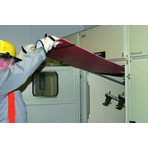
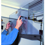
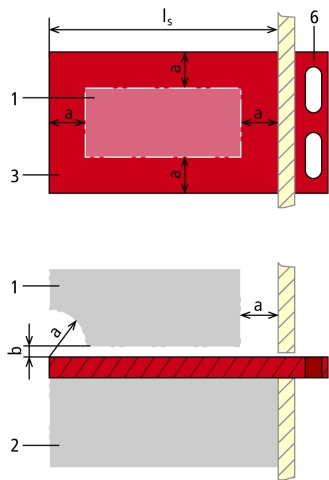
Figure 1 and Figure 2
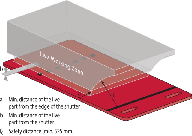

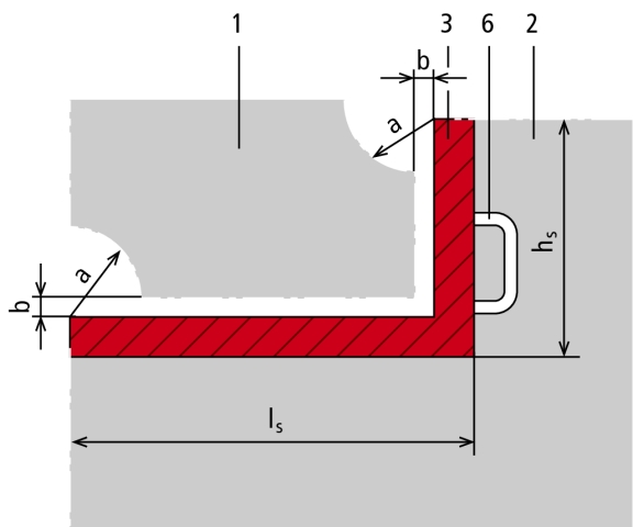
- According to the five safety rules, adjacent parts are parts situated in the vicinity zone. If parts of an installation near the work location cannot be disconnected, additional safety measures must be taken before starting work as is the case with work in the vicinity of live parts. Insulating protective shutters according to DIN VDE 0682-522 are used to provide protection against accidental contact with live parts of an installation. They are portable and inserted under live conditions by hand or by using an operating stick. Insulating protective shutters are designed for short-term use in indoor electrical installations according to DIN VDE 0101 with voltages from 1 to 36 kV a.c. at nominal frequencies below 100 Hz to provide protection against direct contact according to DIN VDE 0105-100 when working in the vicinity of live parts. When used in medium-voltage installations, insulating protective shutters might have to be adapted, for example if it is not possible to insert shutters in the live working zone without risk due to unfavourably located drives, switch components or isolating plates. In such cases, a standard-compliant solution can be found by cutting out parts of the insulating protective shutter or cutting it to size. For that purpose, technical details must be provided. We have developed a special template for insulating protective shutters which can be used, for example, to mark the exact location of cut-outs.For enquiries and orders, please fill in the template on our website www.dehn-international.com.NoteInsulating protective shutters do not protect against re-connection. The protected area is the area which is separated from the area containing live parts by the insulating protective shutter. The minimum distances shown in the above table between shutters / shutter edges and live parts must be observed.The protective part (with length IS and, if required, height hS) of insulating protective shutters is the part that provides protection against accidental contact with live parts. It is fitted with either a handle or a coupling for attaching an operating stick.Outside the live working zone, the following gaps are permissible between shutter edge and cell wall:
- Up to 10 mm without restriction
- Up to 40 mm, if the distance between the shutter edge and the live working zone is at least 100 mm
- Up to 100 mm near a switch subconstruction
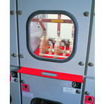
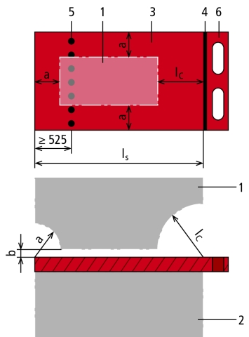
Figure 3 and Figure 4
Due to the various designs of switchgear installations, DIN VDE 0682-552 defines four different basic types of protective shutters:
A1, safety distance provides protection during inserting and removing insulating protective shutters
A2, protective section provides protection during inserting and removing insulating protective shutters
A1, safety distance provides protection during inserting and removing insulating protective shutters
A2, protective section provides protection during inserting and removing insulating protective shutters
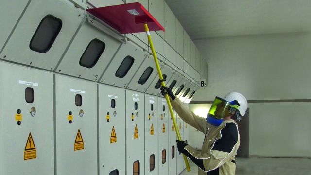
Figure 5 and Figure 6
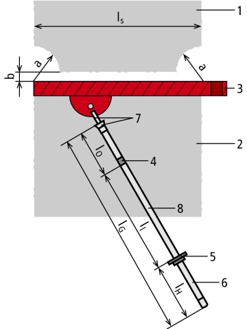
A3, operating stick provides protection during inserting and removing insulating protective shutters
A4, protective device installed in the installation provides protection during inserting and removing insulating protective shutters
1 Live working zone
2 Protected area
3 Protective section with length lS (and height hS)
4 Limit mark or red ring
5 Guide mark / hand guard
6 Handle
7 Coupling
8 Insulating element of the operating stick with length ll
lG Total length of the operating stick
lO Length of the top section of the operating stick
lH Length of the handle of the operating stick
ll Length of the insulating element of the operating stick
lS Length of the protective section
lC Safety distance
a Minimum distance of live parts from the edge of the insulating protective shutter
b Minimum distance of live parts from the insulating protective shutter