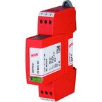
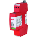
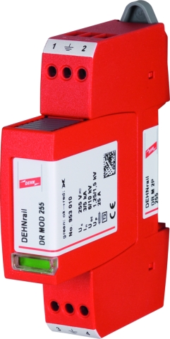
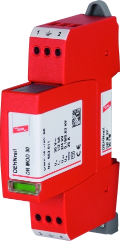
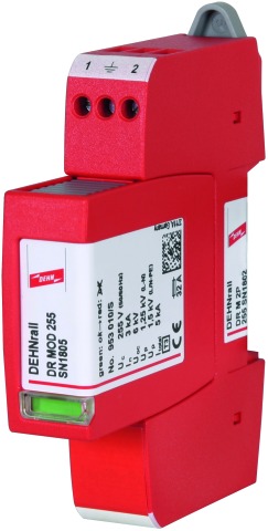
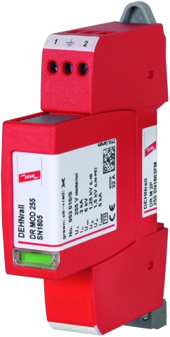
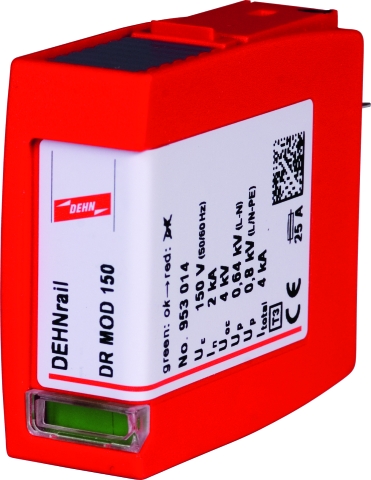
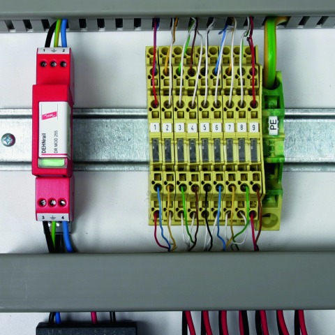
DEHNrail modular
Pluggable two-pole Surge Arrester
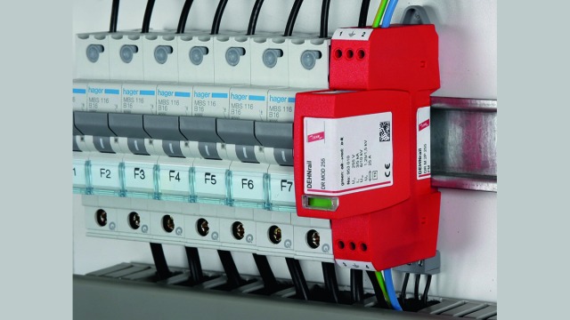
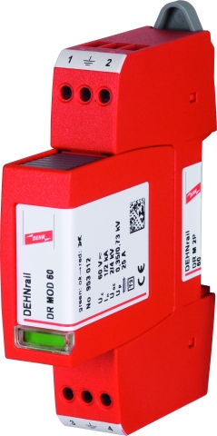
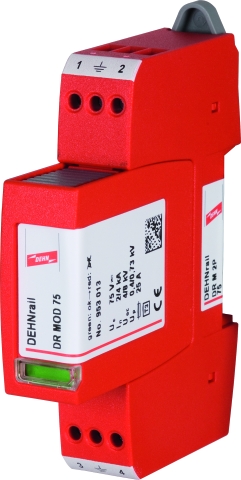
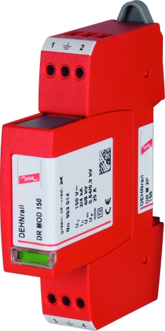
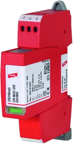
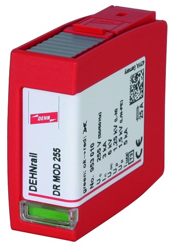
- Two-pole surge arrester consisting of a base part and a plug-in protection module
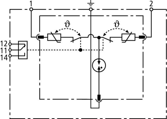
- High discharge capacity due to heavy-duty zinc oxide varistor / spark gap combination
- Energy coordination with other arresters of the Red/Line product family
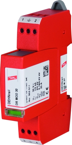
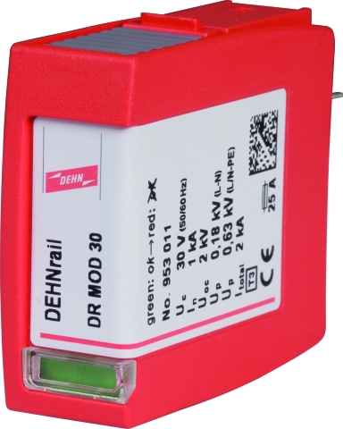
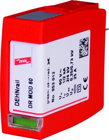
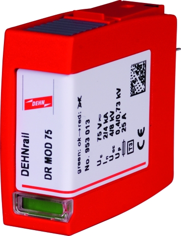
- Operating state / fault indication by green / red indicator flag in the inspection window
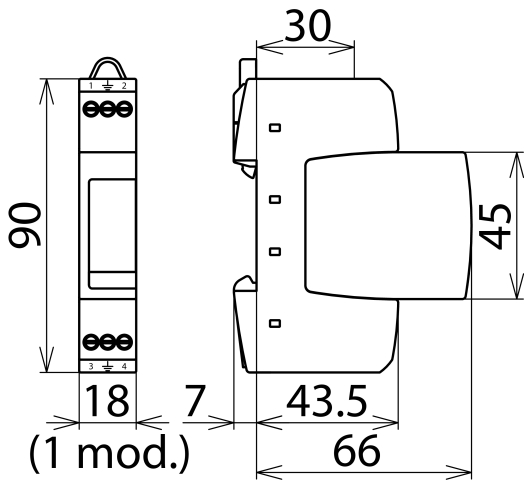
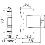
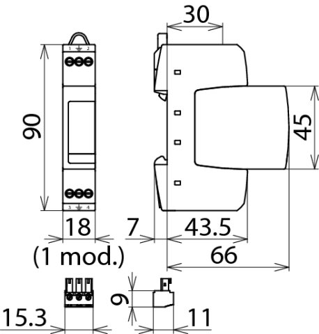
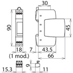
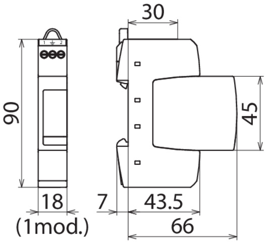
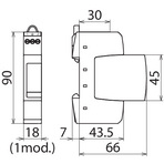
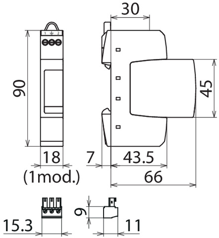
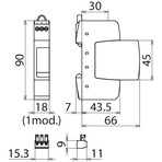
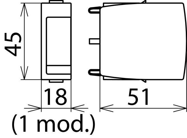
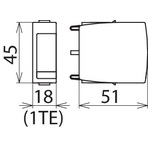
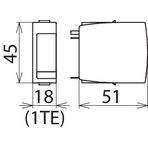
- Narrow (modular) design according to DIN 43880
- Easy replacement of protection modules due to module locking system with module release button
- Vibration and shock-tested according to EN 60068-2
Version
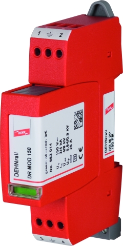
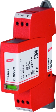
DEHNrail M 2P ...: Two-pole surge arrester consisting of a base part and a plug-in protection module
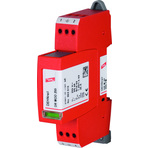
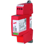
DEHNrail M 2P ... FM: With remote signalling contact for monitoring device (floating changeover contact)
DEHNrail M 2P ... FM: With remote signalling contact for monitoring device (floating changeover contact)
Details
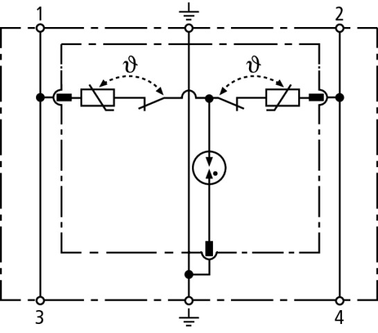
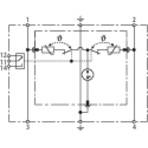
The modular devices of the DEHNrail M product family stand out due to their high performance parameters and straightforward Red/Line design. The devices combine safety and ease of use in a single module. The low voltage protection level and the comprehensive protection against common-mode and differential-mode interference make them ideal for protecting terminal equipment in industrial electronics environments. The input and output terminals for series connection and the protective circuit designed for high load currents underline this concept.
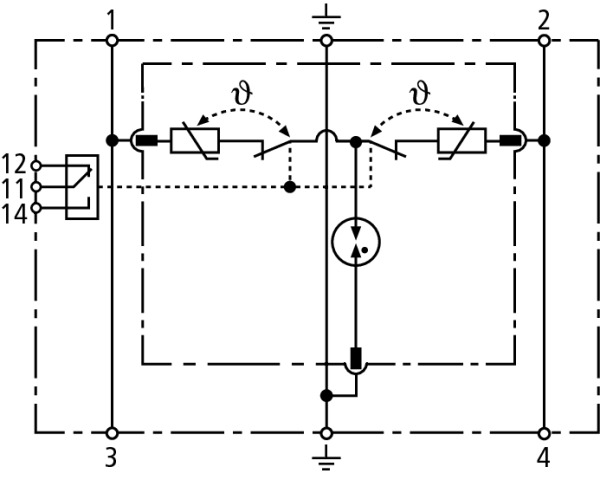
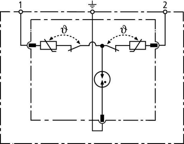
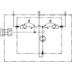
The very compact design of the DEHNrail M surge arresters includes the fault-proof Y protective circuit and a combined SPD monitoring and disconnection device.
The base part and protection module are coded to ensure against installing an incorrect module.
The unique module locking system of the DEHNrail M product family fixes the protection module to the base part. Neither vibration during transport nor the electrodynamic forces of discharge can loosen the connection.
In the event of the protective circuit being overloaded, the protection modules can be easily replaced without tools by simply pressing the module release button.
In addition to the standard visual indication with green and red indicator flags, DEHNrail M ... FM devices feature a three-pole remote signalling terminal. With its floating changeover contact, the remote signal can be used as a break or make contact according to the particular circuit concept.