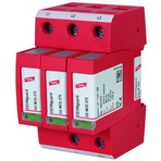
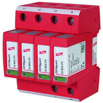
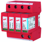
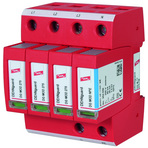
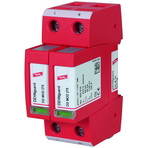
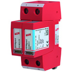
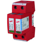
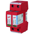
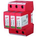
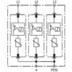
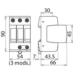
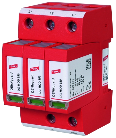
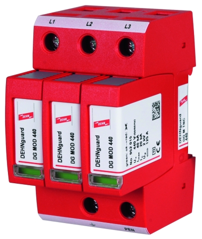
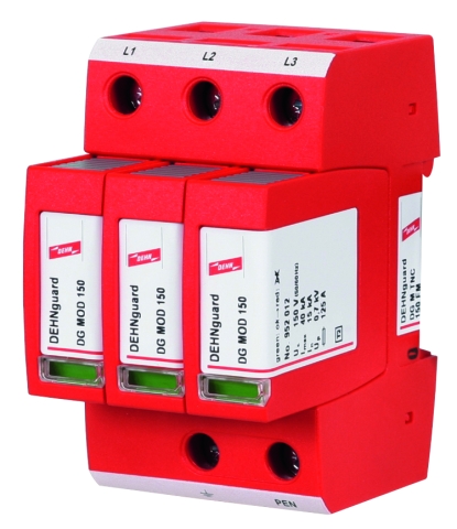
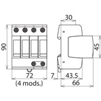
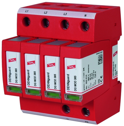
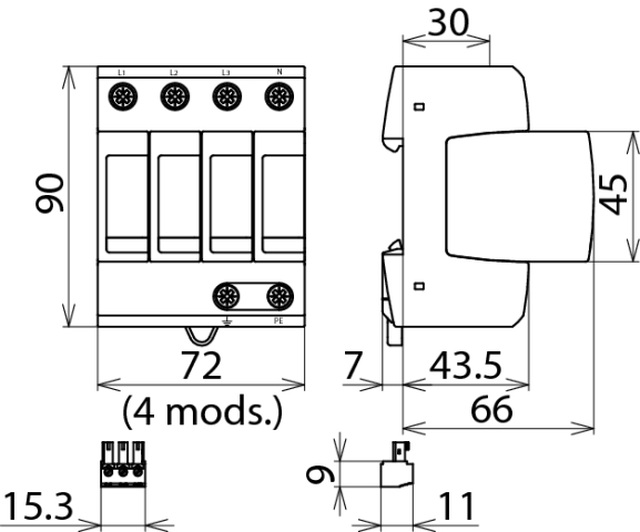
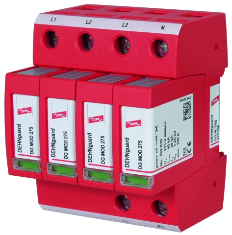
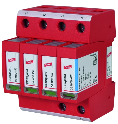
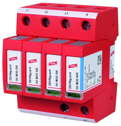
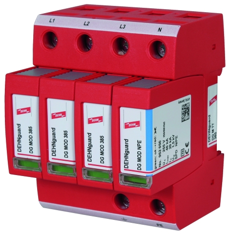
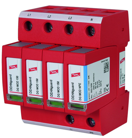
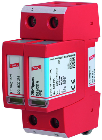
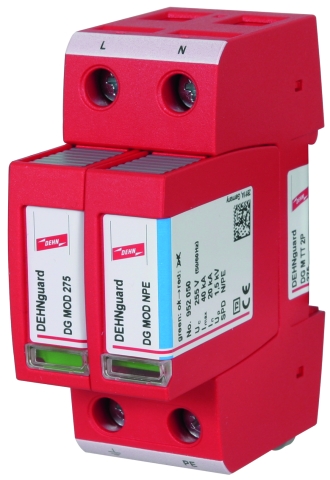
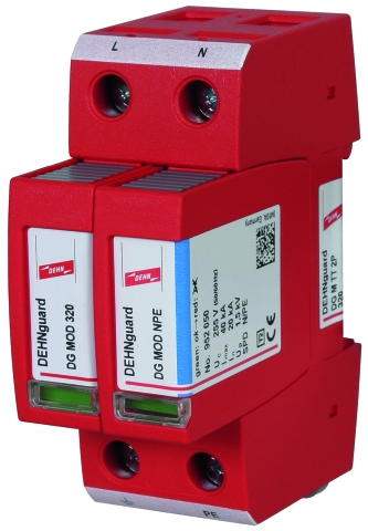
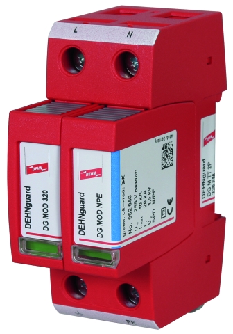
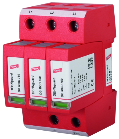
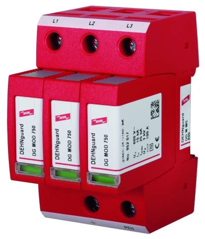
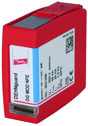
DEHNguard® modular

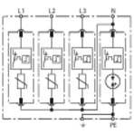
Modular multipole Surge Arrester

For protecting low-voltage consumer's installations against surges. For installation in conformity with the lightning protection zone concept at the boundaries from 0B– 1 and higher.
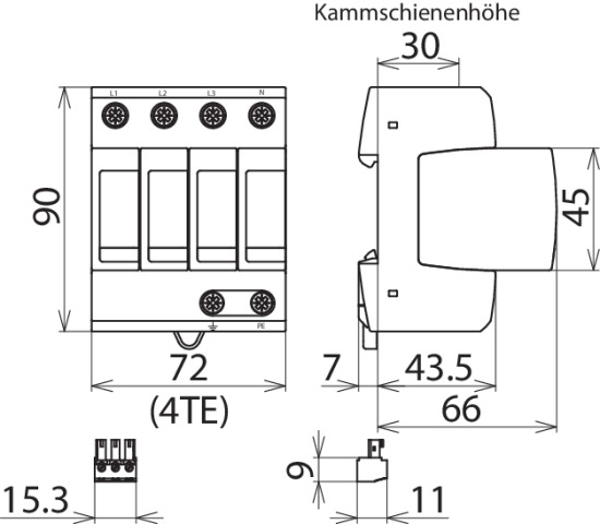
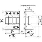
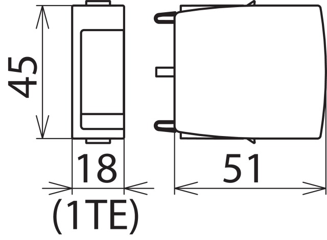
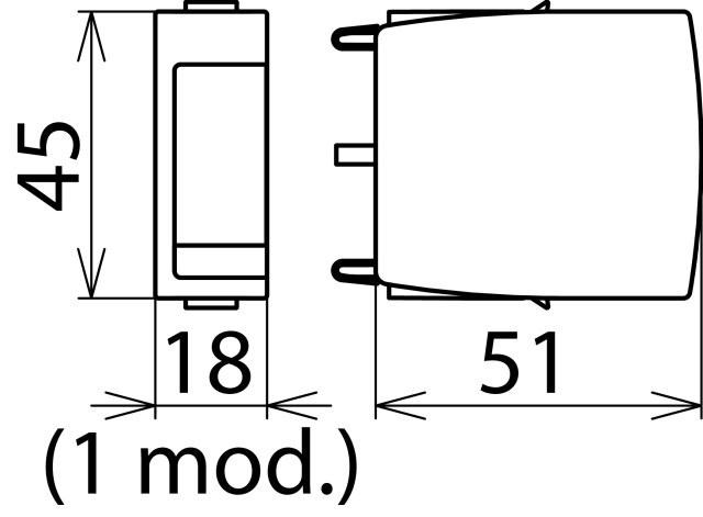
  • Prewired complete unit consisting of a base part and plug-in protection modules
  • Energy coordination with other arresters of the Red/Line product family
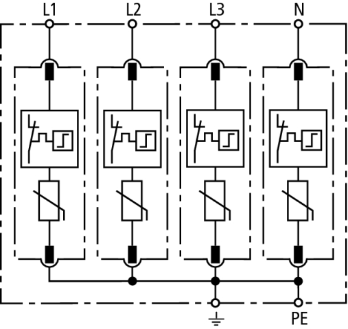
  • High discharge capacity due to heavy-duty zinc oxide varistors / spark gaps
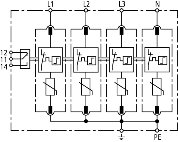
  • High reliability due to "Thermo Dynamic Control" SPD monitoring device
  • Easy replacement of protection modules without tools due to module locking system with module release button
  • Vibration and shock-tested according to EN 60068-2

Version

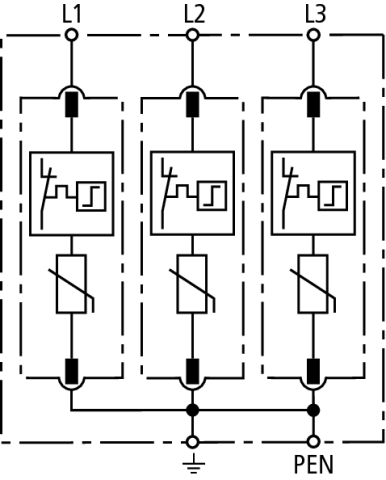
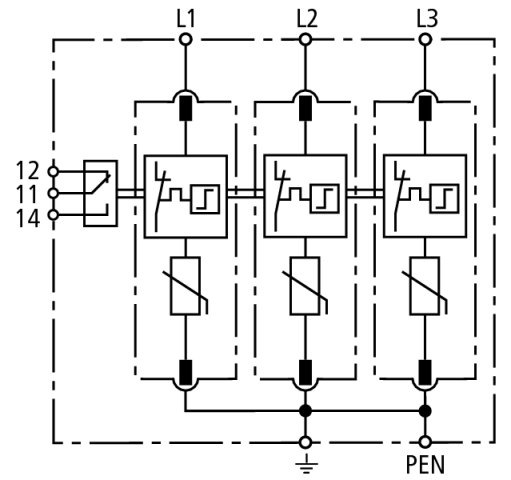
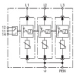
DEHNguard M TNC ...: Modular surge arrester for use in TN-C systems
DEHNguard M TNS ...: Modular surge arrester for use in TN-S systems
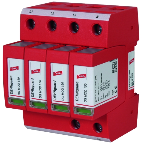
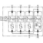
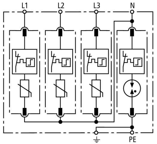
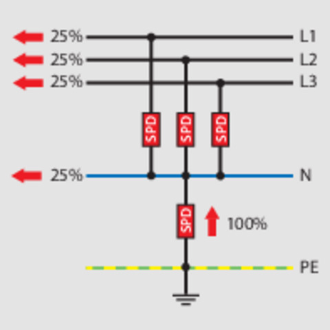
DEHNguard M H TT ...: Modular surge arrester with an increased discharge capacity for use in TT and TN-S systems (3+1 configuration)
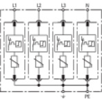
DEHNguard M TT ...: Modular surge arrester for use in TT and TN-S systems (3+1 configuration)
DEHNguard M TN ...: Modular surge arrester for use in single-phase TN systems
DEHNguard M H TT 2P ...: Modular surge arrester with an increased discharge capacity for single-phase TT and TN systems (1+1 configuration)
DEHNguard M TT 2P ...: Modular surge arrester for use in single-phase TT and TN systems (1+1 configuration)
DEHNguard M WE ...: Modular surge arrester especially for use in wind turbines
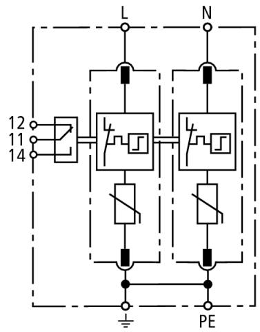
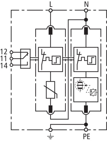
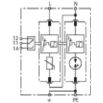
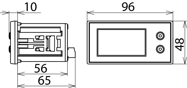
DEHNguard M ... FM: With remote signalling contact for monitoring device (floating changeover contact)

Details

3+1 configuration with an increased discharge capacity 4 x 20 kA = 80 kA.
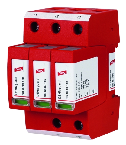
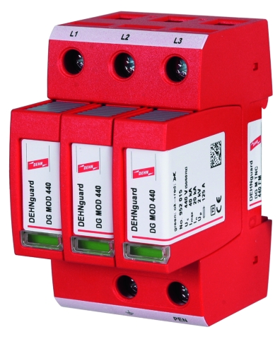
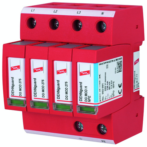
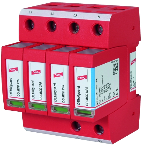
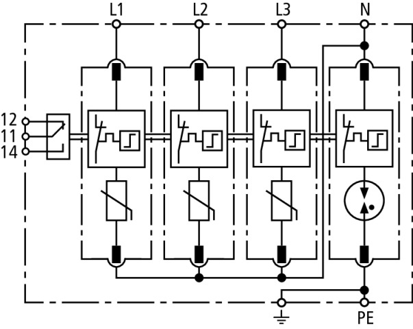
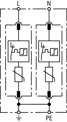
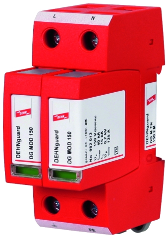
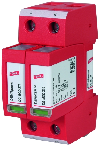
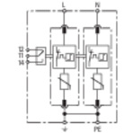
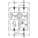
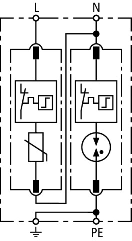
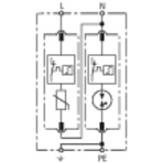
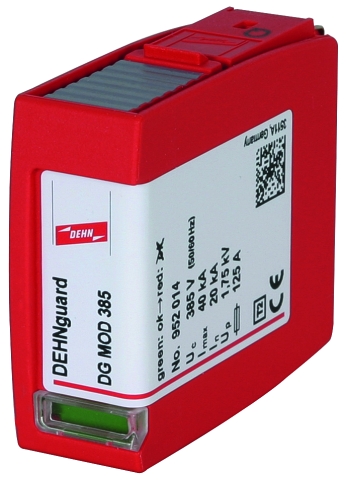
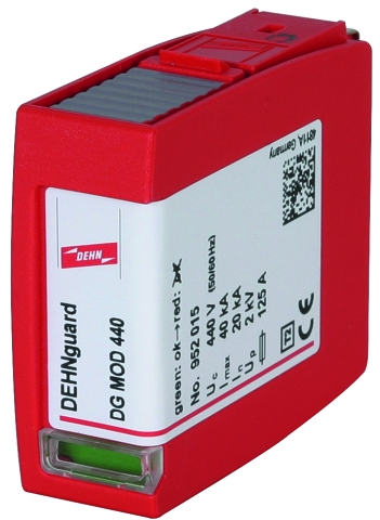
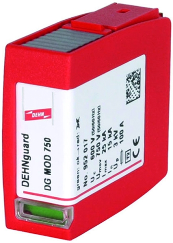
Featuring the functional Red/Line family design, the modular DEHNguard M ... surge arresters set new standards in terms of safety and ease of use. The proven protective circuit with heavy-duty zinc oxide varistors in combination with the dual "Thermo Dynamic Control" monitoring device are characteristic of the DEHNguard technology.

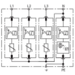
A variety of features shows that both reliable surge protection and equipment safety are key elements of the modular DEHNguard surge arresters. The application-based product designation, which makes it considerably easier to choose the correct device for the relevant application, as well as the unique module locking system stand for fulfilling the most stringent safety requirements. The module locking system firmly fixes the protection modules to the base part. Neither vibration during transport nor the enormous forces of discharge can loosen the protection modules. Nevertheless, they can be easily replaced without tools by simply pressing the easy-to use module release button of the protection modules. Each protective circuit of the multipole surge arresters and each protection module are mechanically coded to ensure against installing an incorrect module.

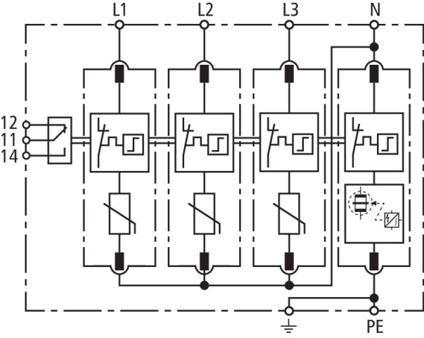
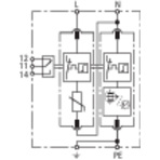
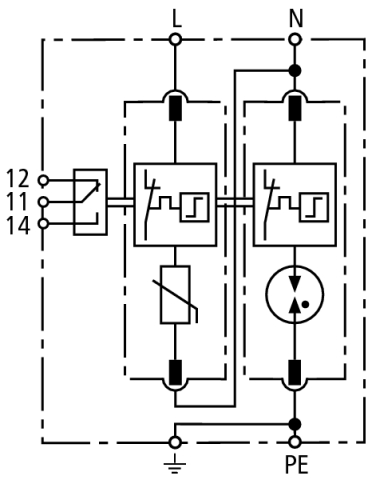
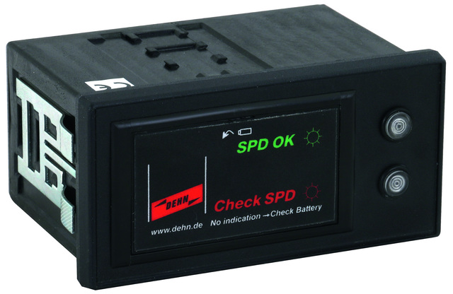
The dual "Thermo Dynamic Control" monitoring device was not only developed on the basis of national and international product standards, but also stands for experience of decades in the world market of surge protective devices and considers many practical applications where arresters might be damaged. As with all DEHN surge arresters with "Thermo Dynamic Control", the surface temperature of the heavy-duty varistor and the intensity of the discharge current are used for evaluation. The visual indicator with green and red indicator flags shows the availability of every protective circuit. Apart from this standard visual indication, DEHNguard M ... FM devices feature a three-pole remote signalling terminal.

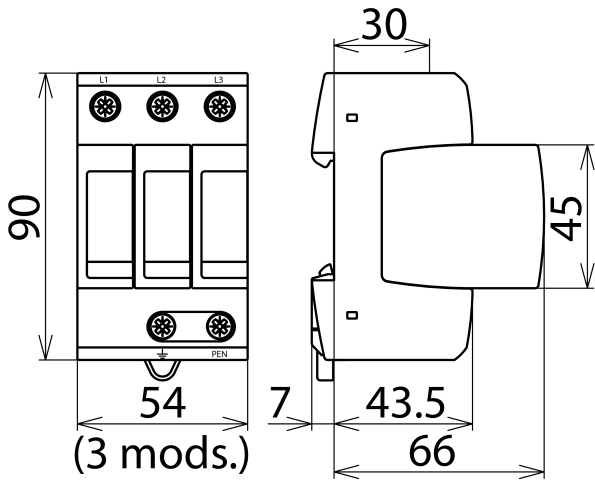
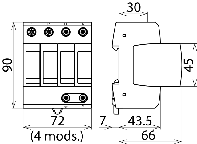
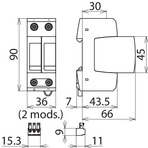
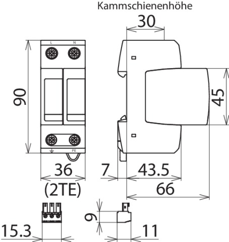
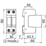
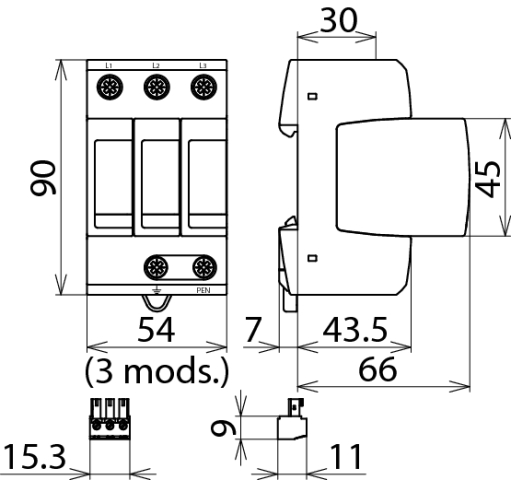
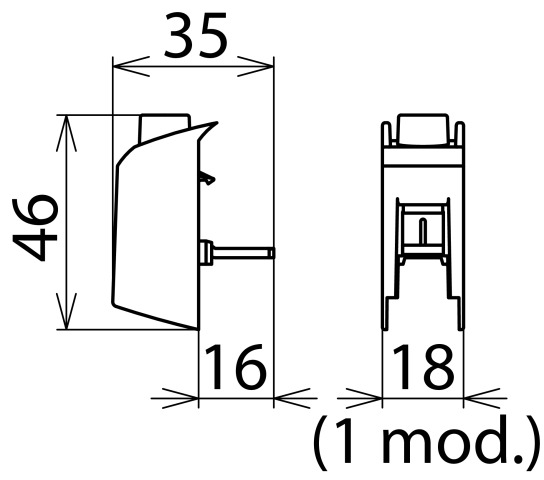
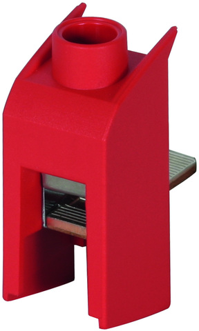
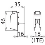
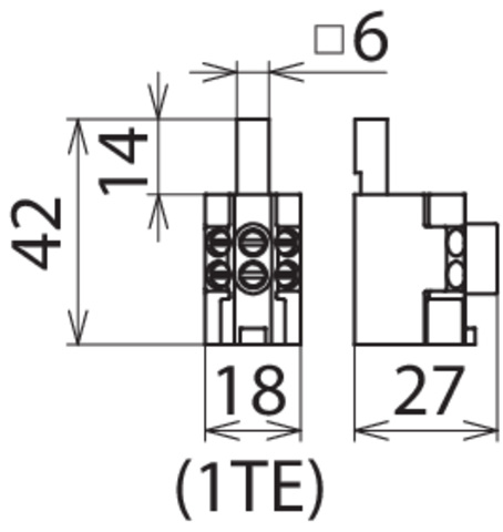
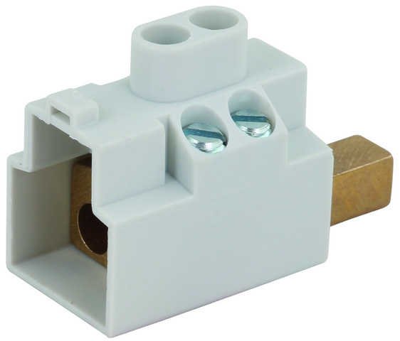
With its floating changeover contact, the remote signal can be used as a make or break contract according to the particular circuit concept. The surge arresters of the modular multipole DEHNguard M family feature multifunctional terminals on a standardised spacing of 1 module for the connection of conductors and busbars, allowing easy wiring with other DIN rail mounted devices. The STAK 25 pin-shaped terminal, which is compatible with all DEHNguard modules, allows optimal series connection according to IEC 60364-5-53.

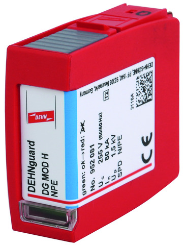
The DEHNguard M H TT … type already meets the requirements of the new VDE 0100-534 standard (Table: Discharge values In in a 3+1 configuration for three-phase systems with increased safety requirements). This table requires at least 40 kA for the N-PE path. Since a discharge capacity of 80 kA was technically feasible, arithmetically correct dimensioning (4 x 20 kA = 80 kA) in combination with the standard varistor-based modules with In = 20 kA is ensured.

Models

DEHNguard M TNC ...

DEHNguard M TNC ... FM

DEHNguard M TNS ...

DEHNguard M TNS ... FM

DEHNguard M H TT ... (FM)

DEHNguard M TT ...

DEHNguard M TT ... FM

DEHNguard M TN ...

DEHNguard M TN ... FM

DEHNguard M H TT 2P ... (FM)

DEHNguard M TT 2P ...

DEHNguard M TT 2P ... FM

DEHNguard M WE ... (FM)

DEHNguard M TNC ...

Basic circuit diagram DG M TNC ...Dimension drawing DG M TNC ...

Modular surge arrester for use in TN-C systems (3+0 configuration).


Specifications

Type
Part No.
SPD according to EN 61643-11 / IEC 61643-11
Energy coordination with terminal equipment (≤ 10 m)
Nominal voltage (a.c.) (UN)
Max. continuous operating voltage (a.c.) (UC)
Nominal discharge current (8/20 µs) (In)
Max. discharge current (8/20 µs) (Imax)
Voltage protection level (UP)
Voltage protection level at 5 kA (UP)
Response time (tA)
Max. mains-side overcurrent protection
Short-circuit withstand capability for max. mains-side overcurrent protection (ISCCR)
Temporary overvoltage (TOV) (UT) – Characteristic
Operating temperature range (TU)
Operating state / fault indication
Number of ports
Cross-sectional area (min.)
Cross-sectional area (max.)
For mounting on
Enclosure material
Place of installation
Degree of protection
Capacity
Approvals
Weight
GTIN
PU
Part No.
  • DG M TNC 150
  • 952 313
  • type 2 / class II
  • type 2 + type 3
  • 120 / 240 V (50 / 60 Hz)
  • 150 V (50 / 60 Hz)
  • 15 kA
  • 40 kA
  • ≤ 0.7 kV
  • ≤ 0.55 kV
  • ≤ 25 ns
  • 125 A gG
  • 50 kArms
  • 175 V / 5 sec. – withstand
  • 230 V / 120 min. – safe failure
  • -40 °C ... +80 °C
  • green / red
  • 1
  • 1.5 mm2 solid / flexible
  • 35 mm2 stranded / 25 mm2 flexible
  • 35 mm DIN rails acc. to EN 60715
  • thermoplastic, red, UL 94 V-0
  • indoor installation
  • IP 20
  • 3 module(s), DIN 43880
  • KEMA, UL
  • 299 g
  • 4013364123939
  • 1 pc(s)
  • 952 313
  • Specifications (PDF)
  • More
  • DG M TNC 275
  • 952 300
  • type 2 / class II
  • type 2 + type 3
  • 230 / 400 V (50 / 60 Hz)
  • 275 V (50 / 60 Hz)
  • 20 kA
  • 40 kA
  • ≤ 1.5 kV
  • ≤ 1 kV
  • ≤ 25 ns
  • 125 A gG
  • 50 kArms
  • 335 V / 5 sec. – withstand
  • 440 V / 120 min. – safe failure
  • -40 °C ... +80 °C
  • green / red
  • 1
  • 1.5 mm2 solid / flexible
  • 35 mm2 stranded / 25 mm2 flexible
  • 35 mm DIN rails acc. to EN 60715
  • thermoplastic, red, UL 94 V-0
  • indoor installation
  • IP 20
  • 3 module(s), DIN 43880
  • KEMA, VDE, UL
  • 334 g
  • 4013364108431
  • 1 pc(s)
  • 952 300
  • Specifications (PDF)
  • More
  • DG M TNC 385
  • 952 314
  • type 2 / class II
  • type 2 + type 3
  • 230 / 400 V (50 / 60 Hz)
  • 385 V (50 / 60 Hz)
  • 20 kA
  • 40 kA
  • ≤ 1.75 kV
  • ≤ 1.35 kV
  • ≤ 25 ns
  • 125 A gG
  • 25 kArms
  • 335 V / 5 sec. – withstand
  • 440 V / 120 min. – withstand
  • -40 °C ... +80 °C
  • green / red
  • 1
  • 1.5 mm2 solid / flexible
  • 35 mm2 stranded / 25 mm2 flexible
  • 35 mm DIN rails acc. to EN 60715
  • thermoplastic, red, UL 94 V-0
  • indoor installation
  • IP 20
  • 3 module(s), DIN 43880
  • KEMA, UL
  • 342 g
  • 4013364124028
  • 1 pc(s)
  • 952 314
  • Specifications (PDF)
  • More
  • DG M TNC 440
  • 952 303
  • type 2 / class II
  • type 2 + type 3
  • 400 / 690 V (50 / 60 Hz)
  • 440 V (50 / 60 Hz)
  • 20 kA
  • 40 kA
  • ≤ 2 kV
  • ≤ 1.7 kV
  • ≤ 25 ns
  • 125 A gG
  • 25 kArms
  • 580 V / 5 sec. – withstand
  • 765 V / 120 min. – safe failure
  • -40 °C ... +80 °C
  • green / red
  • 1
  • 1.5 mm2 solid / flexible
  • 35 mm2 stranded / 25 mm2 flexible
  • 35 mm DIN rails acc. to EN 60715
  • thermoplastic, red, UL 94 V-0
  • indoor installation
  • IP 20
  • 3 module(s), DIN 43880
  • KEMA, UL
  • 355 g
  • 4013364120709
  • 1 pc(s)
  • 952 303
  • Specifications (PDF)
  • More

DEHNguard M TNC ... FM

Basic circuit diagram DG M TNC ... FMDimension drawing DG M TNC ... FM

Modular surge arrester for use in TN-C systems (3+0 configuration); with floating changeover contact.


Specifications

Type
Part No.
SPD according to EN 61643-11 / IEC 61643-11
Energy coordination with terminal equipment (≤ 10 m)
Nominal voltage (a.c.) (UN)
Max. continuous operating voltage (a.c.) (UC)
Nominal discharge current (8/20 µs) (In)
Max. discharge current (8/20 µs) (Imax)
Voltage protection level (UP)
Voltage protection level at 5 kA (UP)
Response time (tA)
Max. mains-side overcurrent protection
Short-circuit withstand capability for max. mains-side overcurrent protection (ISCCR)
Temporary overvoltage (TOV) (UT) – Characteristic
Operating temperature range (TU)
Operating state / fault indication
Number of ports
Cross-sectional area (min.)
Cross-sectional area (max.)
For mounting on
Enclosure material
Place of installation
Degree of protection
Capacity
Approvals
Type of remote signalling contact
Switching capacity (a.c.)
Switching capacity (d.c.)
Cross-sectional area for remote signalling terminals
Weight
GTIN
PU
Part No.
  • DG M TNC 150 FM
  • 952 318
  • type 2 / class II
  • type 2 + type 3
  • 120 / 240 V (50 / 60 Hz)
  • 150 V (50 / 60 Hz)
  • 15 kA
  • 40 kA
  • ≤ 0.7 kV
  • ≤ 0.55 kV
  • ≤ 25 ns
  • 125 A gG
  • 50 kArms
  • 175 V / 5 sec. – withstand
  • 230 V / 120 min. – safe failure
  • -40 °C ... +80 °C
  • green / red
  • 1
  • 1.5 mm2 solid / flexible
  • 35 mm2 stranded / 25 mm2 flexible
  • 35 mm DIN rails acc. to EN 60715
  • thermoplastic, red, UL 94 V-0
  • indoor installation
  • IP 20
  • 3 module(s), DIN 43880
  • KEMA, UL
  • changeover contact
  • 250 V / 0.5 A
  • 250 V / 0.1 A; 125 V / 0.2 A; 75 V / 0.5 A
  • max. 1.5 mm2 solid / flexible
  • 306 g
  • 4013364124011
  • 1 pc(s)
  • 952 318
  • Specifications (PDF)
  • More
  • DG M TNC 275 FM
  • 952 305
  • type 2 / class II
  • type 2 + type 3
  • 230 / 400 V (50 / 60 Hz)
  • 275 V (50 / 60 Hz)
  • 20 kA
  • 40 kA
  • ≤ 1.5 kV
  • ≤ 1 kV
  • ≤ 25 ns
  • 125 A gG
  • 50 kArms
  • 335 V / 5 sec. – withstand
  • 440 V / 120 min. – safe failure
  • -40 °C ... +80 °C
  • green / red
  • 1
  • 1.5 mm2 solid / flexible
  • 35 mm2 stranded / 25 mm2 flexible
  • 35 mm DIN rails acc. to EN 60715
  • thermoplastic, red, UL 94 V-0
  • indoor installation
  • IP 20
  • 3 module(s), DIN 43880
  • KEMA, VDE, UL
  • changeover contact
  • 250 V / 0.5 A
  • 250 V / 0.1 A; 125 V / 0.2 A; 75 V / 0.5 A
  • max. 1.5 mm2 solid / flexible
  • 328 g
  • 4013364108448
  • 1 pc(s)
  • 952 305
  • Specifications (PDF)
  • More
  • DG M TNC 385 FM
  • 952 319
  • type 2 / class II
  • type 2 + type 3
  • 230 / 400 V (50 / 60 Hz)
  • 385 V (50 / 60 Hz)
  • 20 kA
  • 40 kA
  • ≤ 1.75 kV
  • ≤ 1.35 kV
  • ≤ 25 ns
  • 125 A gG
  • 25 kArms
  • 335 V / 5 sec. – withstand
  • 440 V / 120 min. – withstand
  • -40 °C ... +80 °C
  • green / red
  • 1
  • 1.5 mm2 solid / flexible
  • 35 mm2 stranded / 25 mm2 flexible
  • 35 mm DIN rails acc. to EN 60715
  • thermoplastic, red, UL 94 V-0
  • indoor installation
  • IP 20
  • 3 module(s), DIN 43880
  • KEMA, UL
  • changeover contact
  • 250 V / 0.5 A
  • 250 V / 0.1 A; 125 V / 0.2 A; 75 V / 0.5 A
  • max. 1.5 mm2 solid / flexible
  • 350 g
  • 4013364124035
  • 1 pc(s)
  • 952 319
  • Specifications (PDF)
  • More
  • DG M TNC 440 FM
  • 952 308
  • type 2 / class II
  • type 2 + type 3
  • 400 / 690 V (50 / 60 Hz)
  • 440 V (50 / 60 Hz)
  • 20 kA
  • 40 kA
  • ≤ 2 kV
  • ≤ 1.7 kV
  • ≤ 25 ns
  • 125 A gG
  • 25 kArms
  • 580 V / 5 sec. – withstand
  • 765 V / 120 min. – safe failure
  • -40 °C ... +80 °C
  • green / red
  • 1
  • 1.5 mm2 solid / flexible
  • 35 mm2 stranded / 25 mm2 flexible
  • 35 mm DIN rails acc. to EN 60715
  • thermoplastic, red, UL 94 V-0
  • indoor installation
  • IP 20
  • 3 module(s), DIN 43880
  • KEMA, UL
  • changeover contact
  • 250 V / 0.5 A
  • 250 V / 0.1 A; 125 V / 0.2 A; 75 V / 0.5 A
  • max. 1.5 mm2 solid / flexible
  • 362 g
  • 4013364120716
  • 1 pc(s)
  • 952 308
  • Specifications (PDF)
  • More

DEHNguard M TNS ...

Basic circuit diagram DG M TNS ...Dimension drawing DG M TNS ...

Modular surge arrester for use in TN-S systems (4+0 configuration).


Specifications

Type
Part No.
SPD according to EN 61643-11 / IEC 61643-11
Energy coordination with terminal equipment (≤ 10 m)
Nominal voltage (a.c.) (UN)
Max. continuous operating voltage (a.c.) (UC)
Nominal discharge current (8/20 µs) (In)
Max. discharge current (8/20 µs) (Imax)
Voltage protection level [L-PE]/[N-PE] (UP)
Voltage protection level [L-PE] / [N-PE] at 5 kA (UP)
Response time (tA)
Max. mains-side overcurrent protection
Short-circuit withstand capability for max. mains-side overcurrent protection (ISCCR)
Temporary overvoltage (TOV) (UT) – Characteristic
Operating temperature range (TU)
Operating state / fault indication
Number of ports
Cross-sectional area (min.)
Cross-sectional area (max.)
For mounting on
Enclosure material
Place of installation
Degree of protection
Capacity
Approvals
Weight
GTIN
PU
Part No.
  • DG M TNS 150
  • 952 403
  • type 2 / class II
  • type 2 + type 3
  • 120 / 240 V (50 / 60 Hz)
  • 150 V (50 / 60 Hz)
  • 15 kA
  • 40 kA
  • ≤ 0.7 / ≤ 0.7 kV
  • ≤ 0.55 / ≤ 0.55 kV
  • ≤ 25 ns
  • 125 A gG
  • 50 kArms
  • 175 V / 5 sec. – withstand
  • 230 V / 120 min. – safe failure
  • -40 °C ... +80 °C
  • green / red
  • 1
  • 1.5 mm2 solid / flexible
  • 35 mm2 stranded / 25 mm2 flexible
  • 35 mm DIN rails acc. to EN 60715
  • thermoplastic, red, UL 94 V-0
  • indoor installation
  • IP 20
  • 4 module(s), DIN 43880
  • KEMA, UL
  • 417 g
  • 4013364128569
  • 1 pc(s)
  • 952 403
  • Specifications (PDF)
  • More
  • DG M TNS 275
  • 952 400
  • type 2 / class II
  • type 2 + type 3
  • 230 / 400 V (50 / 60 Hz)
  • 275 V (50 / 60 Hz)
  • 20 kA
  • 40 kA
  • ≤ 1.5 / ≤ 1.5 kV
  • ≤ 1 / ≤ 1 kV
  • ≤ 25 ns
  • 125 A gG
  • 50 kArms
  • 335 V / 5 sec. – withstand
  • 440 V / 120 min. – safe failure
  • -40 °C ... +80 °C
  • green / red
  • 1
  • 1.5 mm2 solid / flexible
  • 35 mm2 stranded / 25 mm2 flexible
  • 35 mm DIN rails acc. to EN 60715
  • thermoplastic, red, UL 94 V-0
  • indoor installation
  • IP 20
  • 4 module(s), DIN 43880
  • KEMA, VDE, UL
  • 414 g
  • 4013364108455
  • 1 pc(s)
  • 952 400
  • Specifications (PDF)
  • More
  • DG M TNS 385
  • 952 404
  • type 2 / class II
  • type 2 + type 3
  • 230 / 400 V (50 / 60 Hz)
  • 385 V (50 / 60 Hz)
  • 20 kA
  • 40 kA
  • ≤ 1.75 / ≤ 1.75 kV
  • ≤ 1.35 / ≤ 1.35 kV
  • ≤ 25 ns
  • 125 A gG
  • 25 kArms
  • 335 V / 5 sec. – withstand
  • 440 V / 120 min. – withstand
  • -40 °C ... +80 °C
  • green / red
  • 1
  • 1.5 mm2 solid / flexible
  • 35 mm2 stranded / 25 mm2 flexible
  • 35 mm DIN rails acc. to EN 60715
  • thermoplastic, red, UL 94 V-0
  • indoor installation
  • IP 20
  • 4 module(s), DIN 43880
  • KEMA, UL
  • 474 g
  • 4013364128545
  • 1 pc(s)
  • 952 404
  • Specifications (PDF)
  • More

DEHNguard M TNS ... FM

Basic circuit diagram DG M TNS ... FMDimension drawing DG M TNS ... FM

Modular surge arrester for use in TN-S systems (4+0 configuration); with floating changeover contact.


Specifications

Type
Part No.
SPD according to EN 61643-11 / IEC 61643-11
Energy coordination with terminal equipment (≤ 10 m)
Nominal voltage (a.c.) (UN)
Max. continuous operating voltage (a.c.) (UC)
Nominal discharge current (8/20 µs) (In)
Max. discharge current (8/20 µs) (Imax)
Voltage protection level [L-PE]/[N-PE] (UP)
Voltage protection level [L-PE] / [N-PE] at 5 kA (UP)
Response time (tA)
Max. mains-side overcurrent protection
Short-circuit withstand capability for max. mains-side overcurrent protection (ISCCR)
Temporary overvoltage (TOV) (UT) – Characteristic
Operating temperature range (TU)
Operating state / fault indication
Number of ports
Cross-sectional area (min.)
Cross-sectional area (max.)
For mounting on
Enclosure material
Place of installation
Degree of protection
Capacity
Approvals
Type of remote signalling contact
Switching capacity (a.c.)
Switching capacity (d.c.)
Cross-sectional area for remote signalling terminals
Weight
GTIN
PU
Part No.
  • DG M TNS 150 FM
  • 952 408
  • type 2 / class II
  • type 2 + type 3
  • 120 / 240 V (50 / 60 Hz)
  • 150 V (50 / 60 Hz)
  • 15 kA
  • 40 kA
  • ≤ 0.7 / ≤ 0.7 kV
  • ≤ 0.55 / ≤ 0.55 kV
  • ≤ 25 ns
  • 125 A gG
  • 50 kArms
  • 175 V / 5 sec. – withstand
  • 230 V / 120 min. – safe failure
  • -40 °C ... +80 °C
  • green / red
  • 1
  • 1.5 mm2 solid / flexible
  • 35 mm2 stranded / 25 mm2 flexible
  • 35 mm DIN rails acc. to EN 60715
  • thermoplastic, red, UL 94 V-0
  • indoor installation
  • IP 20
  • 4 module(s), DIN 43880
  • KEMA, UL
  • changeover contact
  • 250 V / 0.5 A
  • 250 V / 0.1 A; 125 V / 0.2 A; 75 V / 0.5 A
  • max. 1.5 mm2 solid / flexible
  • 426 g
  • 4013364128576
  • 1 pc(s)
  • 952 408
  • Specifications (PDF)
  • More
  • DG M TNS 275 FM
  • 952 405
  • type 2 / class II
  • type 2 + type 3
  • 230 / 400 V (50 / 60 Hz)
  • 275 V (50 / 60 Hz)
  • 20 kA
  • 40 kA
  • ≤ 1.5 / ≤ 1.5 kV
  • ≤ 1 / ≤ 1 kV
  • ≤ 25 ns
  • 125 A gG
  • 50 kArms
  • 335 V / 5 sec. – withstand
  • 440 V / 120 min. – safe failure
  • -40 °C ... +80 °C
  • green / red
  • 1
  • 1.5 mm2 solid / flexible
  • 35 mm2 stranded / 25 mm2 flexible
  • 35 mm DIN rails acc. to EN 60715
  • thermoplastic, red, UL 94 V-0
  • indoor installation
  • IP 20
  • 4 module(s), DIN 43880
  • KEMA, VDE, UL
  • changeover contact
  • 250 V / 0.5 A
  • 250 V / 0.1 A; 125 V / 0.2 A; 75 V / 0.5 A
  • max. 1.5 mm2 solid / flexible
  • 453 g
  • 4013364108462
  • 1 pc(s)
  • 952 405
  • Specifications (PDF)
  • More
  • DG M TNS 385 FM
  • 952 409
  • type 2 / class II
  • type 2 + type 3
  • 230 / 400 V (50 / 60 Hz)
  • 385 V (50 / 60 Hz)
  • 20 kA
  • 40 kA
  • ≤ 1.75 / ≤ 1.75 kV
  • ≤ 1.35 / ≤ 1.35 kV
  • ≤ 25 ns
  • 125 A gG
  • 25 kArms
  • 335 V / 5 sec. – withstand
  • 440 V / 120 min. – withstand
  • -40 °C ... +80 °C
  • green / red
  • 1
  • 1.5 mm2 solid / flexible
  • 35 mm2 stranded / 25 mm2 flexible
  • 35 mm DIN rails acc. to EN 60715
  • thermoplastic, red, UL 94 V-0
  • indoor installation
  • IP 20
  • 4 module(s), DIN 43880
  • KEMA, UL
  • changeover contact
  • 250 V / 0.5 A
  • 250 V / 0.1 A; 125 V / 0.2 A; 75 V / 0.5 A
  • max. 1.5 mm2 solid / flexible
  • 482 g
  • 4013364128552
  • 1 pc(s)
  • 952 409
  • Specifications (PDF)
  • More

DEHNguard M H TT ... (FM)

Basic circuit diagram DG M H TT 275 (FM)Dimension drawing DG M H TT 275 (FM)

Modular surge arrester with a high total discharge capacity in the N-PE path for TT and TN-S systems (3+1 configuration); meets the increased safety requirements according to the new VDE 0100-534 standard for use at the origin at the electrical installation; with floating remote signalling contact.


Specifications

Type
Part No.
SPD according to EN 61643-11 / IEC 61643-11
Energy coordination with terminal equipment (≤ 10 m)
Nominal voltage (a.c.) (UN)
Max. continuous operating voltage (a.c.) [L-N] (UC)
Max. continuous operating voltage (a.c.) [N-PE] (UC)
Nominal discharge current (8/20 µs) [L-N] (In)
Nominal discharge current (8/20 µs) [N-PE] (In)
Max. discharge current (8/20 µs) [L-N] (Imax)
Max. discharge current (8/20 µs) [N-PE] (Imax)
Voltage protection level [L-N]/[N-PE] (UP)
Voltage protection level [L-N] / [N-PE] at 5 kA (UP)
Follow current extinguishing capability [N-PE] (Ifi)
Response time [L-N] (tA)
Response time [N-PE] (tA)
Max. mains-side overcurrent protection
Short-circuit withstand capability for max. mains-side overcurrent protection (ISCCR)
Temporary overvoltage (TOV) [L-N] (UT) – Characteristic
Temporary overvoltage (TOV) [N-PE] (UT) – Characteristic
Operating temperature range (TU)
Operating state / fault indication
Number of ports
Cross-sectional area (min.)
Cross-sectional area (max.)
For mounting on
Enclosure material
Place of installation
Degree of protection
Capacity
Approvals
Type of remote signalling contact
Switching capacity (a.c.)
Switching capacity (d.c.)
Cross-sectional area for remote signalling terminals
Weight
GTIN
PU
Part No.
  • DG M H TT 275
  • 952 381
  • type 2 / class II
  • type 2 + type 3
  • 230 / 400 V (50 / 60 Hz)
  • 275 V (50 / 60 Hz)
  • 255 V (50 / 60 Hz)
  • 20 kA
  • 80 kA
  • 40 kA
  • 120 kA
  • ≤ 1.5 / ≤ 1.5 kV
  • ≤ 1 / ≤ 1.5 kV
  • 100 Arms
  • ≤ 25 ns
  • ≤ 100 ns
  • 125 A gG
  • 50 kArms
  • 335 V / 5 sec. – withstand
  • 440 V / 120 min. – safe failure
  • 1200 V / 200 ms – withstand
  • -40 °C ... +80 °C
  • green / red
  • 1
  • 1.5 mm2 solid / flexible
  • 35 mm2 stranded / 25 mm2 flexible
  • 35 mm DIN rails acc. to EN 60715
  • thermoplastic, red, UL 94 V-0
  • indoor installation
  • IP 20
  • 4 module(s), DIN 43880
  • KEMA
  •  
  •  
  •  
  •  
  • 405 g
  • 4013364318144
  • 1 pc(s)
  • 952 381
  • Specifications (PDF)
  • More
  • DG M H TT 275 FM
  • 952 385
  • type 2 / class II
  • type 2 + type 3
  • 230 / 400 V (50 / 60 Hz)
  • 275 V (50 / 60 Hz)
  • 255 V (50 / 60 Hz)
  • 20 kA
  • 80 kA
  • 40 kA
  • 120 kA
  • ≤ 1.5 / ≤ 1.5 kV
  • ≤ 1 / ≤ 1.5 kV
  • 100 Arms
  • ≤ 25 ns
  • ≤ 100 ns
  • 125 A gG
  • 50 kArms
  • 335 V / 5 sec. – withstand
  • 440 V / 120 min. – safe failure
  • 1200 V / 200 ms – withstand
  • -40 °C ... +80 °C
  • green / red
  • 1
  • 1.5 mm2 solid / flexible
  • 35 mm2 stranded / 25 mm2 flexible
  • 35 mm DIN rails acc. to EN 60715
  • thermoplastic, red, UL 94 V-0
  • indoor installation
  • IP 20
  • 4 module(s), DIN 43880
  • KEMA
  • changeover contact
  • 250 V / 0.5 A
  • 250 V / 0.1 A; 125 V / 0.2 A; 75 V / 0.5 A
  • max. 1.5 mm2 solid / flexible
  • 415 g
  • 4013364318137
  • 1 pc(s)
  • 952 385
  • Specifications (PDF)
  • More
    • Further Pictures
      Basic circuit diagram DG M H TT 275 FM
      open PDF
      Dimension drawing DG M H TT 275 FM
      open PDF
      Further Information
      Product Specifications (Text)

      Back

      DEHNguard M H TT 275 FM surge arrester
      4-pole, modular surge arrester with an increased discharge capacity for230/400 V TT and TN-
      S systems, 4 mods.
      With remote signalling contact for control device 
      SPD Type 2 according to EN 61643-11
      Max. continuous voltage:              275 V ac
      Voltage protection level:               <= 1.5 kV
      Nominal discharge current [L-N]:   20 kA
      Nominal discharge current [N-PE]: 80 kA
      Short circuit withstand capability:  50 kArms
      Energy-coordinated according to  
      IEC 62305-4 of the Red/Line family
      Operating state and fault indication
      

      delivery and installation.

      Brand: DEHN
      Type: DG M H TT 275 FM
      Part No.: 952 385

      or equivalent.
      Installation Instructions
      Certificates
      CE_DG_M_H_TT_275_FM
      2197751.01
      CAD-Data for registered Users
      952405.stp
      952405.igs
      952405.jt
      952405.dwg
      952405m_E.dxf

DEHNguard M TT ...

Basic circuit diagram DG M TT ...Dimension drawing DG M TT ...

Modular surge arrester for use in TT and TN-S systems (3+1 configuration).


Specifications

Type
Part No.
SPD according to EN 61643-11 / IEC 61643-11
Energy coordination with terminal equipment (≤ 10 m)
Nominal voltage (a.c.) (UN)
Max. continuous operating voltage (a.c.) [L-N] (UC)
Max. continuous operating voltage (a.c.) [N-PE] (UC)
Nominal discharge current (8/20 µs) (In)
Max. discharge current (8/20 µs) (Imax)
Lightning impulse current (10/350 µs) [N-PE] (Iimp)
Voltage protection level [L-N]/[N-PE] (UP)
Voltage protection level [L-N] / [N-PE] at 5 kA (UP)
Follow current extinguishing capability [N-PE] (Ifi)
Response time [L-N] (tA)
Response time [N-PE] (tA)
Max. mains-side overcurrent protection
Short-circuit withstand capability for max. mains-side overcurrent protection (ISCCR)
Temporary overvoltage (TOV) [L-N] (UT) – Characteristic
Temporary overvoltage (TOV) [N-PE] (UT) – Characteristic
Operating temperature range (TU)
Operating state / fault indication
Number of ports
Cross-sectional area (min.)
Cross-sectional area (max.)
For mounting on
Enclosure material
Place of installation
Degree of protection
Capacity
Approvals
Extended technical data:
Voltage protection level [L-PE] (UP)
Weight
GTIN
PU
Part No.
  • DG M TT 150
  • 952 323
  • type 2 / class II
  • type 2 + type 3
  • 120 / 240 V (50 / 60 Hz)
  • 150 V (50 / 60 Hz)
  • 255 V (50 / 60 Hz)
  • 15 kA
  • 40 kA
  • 12 kA
  • ≤ 0.7 / ≤ 1.5 kV
  • ≤ 0.55 / ≤ 1.5  kV
  • 100 Arms
  • ≤ 25 ns
  • ≤ 100 ns
  • 125 A gG
  • 50 kArms
  • 175 V / 5 sec. – withstand
  • 230 V / 120 min. – safe failure
  • 1200 V / 200 ms – withstand
  • -40 °C ... +80 °C
  • green / red
  • 1
  • 1.5 mm2 solid / flexible
  • 35 mm2 stranded / 25 mm2 flexible
  • 35 mm DIN rails acc. to EN 60715
  • thermoplastic, red, UL 94 V-0
  • indoor installation
  • IP 20
  • 4 module(s), DIN 43880
  •  
  • ---------------------------------
  • 1.5 kV
  • 381 g
  • 4013364133235
  • 1 pc(s)
  • 952 323
  • Specifications (PDF)
  • More
  • DG M TT 275
  • 952 310
  • type 2 / class II
  • type 2 + type 3
  • 230 / 400 V (50 / 60 Hz)
  • 275 V (50 / 60 Hz)
  • 255 V (50 / 60 Hz)
  • 20 kA
  • 40 kA
  • 12 kA
  • ≤ 1.5 / ≤ 1.5 kV
  • ≤ 1 / ≤ 1.5 kV
  • 100 Arms
  • ≤ 25 ns
  • ≤ 100 ns
  • 125 A gG
  • 50 kArms
  • 335 V / 5 sec. – withstand
  • 440 V / 120 min. – safe failure
  • 1200 V / 200 ms – withstand
  • -40 °C ... +80 °C
  • green / red
  • 1
  • 1.5 mm2 solid / flexible
  • 35 mm2 stranded / 25 mm2 flexible
  • 35 mm DIN rails acc. to EN 60715
  • thermoplastic, red, UL 94 V-0
  • indoor installation
  • IP 20
  • 4 module(s), DIN 43880
  • KEMA, VDE, UL
  • ---------------------------------
  • 1.5 kV
  • 405 g
  • 4013364108479
  • 1 pc(s)
  • 952 310
  • Specifications (PDF)
  • More
  • DG M TT 320
  • 952 320
  • type 2 / class II
  • type 2 + type 3
  • 230 / 400 V (50 / 60 Hz)
  • 320 V (50 / 60 Hz)
  • 255 V (50 / 60 Hz)
  • 20 kA
  • 40 kA
  • 12 kA
  • ≤ 1.5 / ≤ 1.5 kV
  • ≤ 1.2 / ≤ 1.5 kV
  • 100 Arms
  • ≤ 25 ns
  • ≤ 100 ns
  • 125 A gG
  • 25 kArms
  • 335 V / 5 sec. – withstand
  • 440 V / 120 min. – safe failure
  • 1200 V / 200 ms – withstand
  • -40 °C ... +80 °C
  • green / red
  • 1
  • 1.5 mm2 solid / flexible
  • 35 mm2 stranded / 25 mm2 flexible
  • 35 mm DIN rails acc. to EN 60715
  • thermoplastic, red, UL 94 V-0
  • indoor installation
  • IP 20
  • 4 module(s), DIN 43880
  • KEMA
  • ---------------------------------
  • 1.75 kV
  • 416 g
  • 4013364126794
  • 1 pc(s)
  • 952 320
  • Specifications (PDF)
  • More
  • DG M TT 385
  • 952 311
  • type 2 / class II
  • type 2 + type 3
  • 230 / 400 V (50 / 60 Hz)
  • 385 V (50 / 60 Hz)
  • 255 V (50 / 60 Hz)
  • 20 kA
  • 40 kA
  • 12 kA
  • ≤ 1.75 / ≤ 1.5 kV
  • ≤ 1.35 / ≤ 1.5 kV
  • 100 Arms
  • ≤ 25 ns
  • ≤ 100 ns
  • 125 A gG
  • 25 kArms
  • 335 V / 5 sec. – withstand
  • 440 V / 120 min. – withstand
  • 1200 V / 200 ms – withstand
  • -40 °C ... +80 °C
  • green / red
  • 1
  • 1.5 mm2 solid / flexible
  • 35 mm2 stranded / 25 mm2 flexible
  • 35 mm DIN rails acc. to EN 60715
  • thermoplastic, red, UL 94 V-0
  • indoor installation
  • IP 20
  • 4 module(s), DIN 43880
  • KEMA, UL
  • ---------------------------------
  • 2.0 kV
  • 432 g
  • 4013364119390
  • 1 pc(s)
  • 952 311
  • Specifications (PDF)
  • More

DEHNguard M TT ... FM

Basic circuit diagram DG M TT ... FMDimension drawing DG M TT ... FM

Modular surge arrester for use in TT and TN-S systems (3+1 configuration); with floating remote signalling contact.


Specifications

Type
Part No.
SPD according to EN 61643-11 / IEC 61643-11
Energy coordination with terminal equipment (≤ 10 m)
Nominal voltage (a.c.) (UN)
Max. continuous operating voltage (a.c.) [L-N] (UC)
Max. continuous operating voltage (a.c.) [N-PE] (UC)
Nominal discharge current (8/20 µs) (In)
Max. discharge current (8/20 µs) (Imax)
Lightning impulse current (10/350 µs) [N-PE] (Iimp)
Voltage protection level [L-N]/[N-PE] (UP)
Voltage protection level [L-N] / [N-PE] at 5 kA (UP)
Follow current extinguishing capability [N-PE] (Ifi)
Response time [L-N] (tA)
Response time [N-PE] (tA)
Max. mains-side overcurrent protection
Short-circuit withstand capability for max. mains-side overcurrent protection (ISCCR)
Temporary overvoltage (TOV) [L-N] (UT) – Characteristic
Temporary overvoltage (TOV) [N-PE] (UT) – Characteristic
Operating temperature range (TU)
Operating state / fault indication
Number of ports
Cross-sectional area (min.)
Cross-sectional area (max.)
For mounting on
Enclosure material
Place of installation
Degree of protection
Capacity
Approvals
Type of remote signalling contact
Switching capacity (a.c.)
Switching capacity (d.c.)
Cross-sectional area for remote signalling terminals
Extended technical data:
Voltage protection level [L-PE] (UP)
Weight
GTIN
PU
Part No.
  • DG M TT 150 FM
  • 952 328
  • type 2 / class II
  • type 2 + type 3
  • 120 / 240 V (50 / 60 Hz)
  • 150 V (50 / 60 Hz)
  • 255 V (50 / 60 Hz)
  • 15 kA
  • 40 kA
  • 12 kA
  • ≤ 0.7 / ≤ 1.5 kV
  • ≤ 0.55 / ≤ 1.5  kV
  • 100 Arms
  • ≤ 25 ns
  • ≤ 100 ns
  • 125 A gG
  • 50 kArms
  • 175 V / 5 sec. – withstand
  • 230 V / 120 min. – safe failure
  • 1200 V / 200 ms – withstand
  • -40 °C ... +80 °C
  • green / red
  • 1
  • 1.5 mm2 solid / flexible
  • 35 mm2 stranded / 25 mm2 flexible
  • 35 mm DIN rails acc. to EN 60715
  • thermoplastic, red, UL 94 V-0
  • indoor installation
  • IP 20
  • 4 module(s), DIN 43880
  • UL
  • changeover contact
  • 250 V / 0.5 A
  • 250 V / 0.1 A; 125 V / 0.2 A; 75 V / 0.5 A
  • max. 1.5 mm2 solid / flexible
  • ---------------------------------
  • 1.5 kV
  • 390 g
  • 4013364133242
  • 1 pc(s)
  • 952 328
  • Specifications (PDF)
  • More
  • DG M TT 275 FM
  • 952 315
  • type 2 / class II
  • type 2 + type 3
  • 230 / 400 V (50 / 60 Hz)
  • 275 V (50 / 60 Hz)
  • 255 V (50 / 60 Hz)
  • 20 kA
  • 40 kA
  • 12 kA
  • ≤ 1.5 / ≤ 1.5 kV
  • ≤ 1 / ≤ 1.5 kV
  • 100 Arms
  • ≤ 25 ns
  • ≤ 100 ns
  • 125 A gG
  • 50 kArms
  • 335 V / 5 sec. – withstand
  • 440 V / 120 min. – safe failure
  • 1200 V / 200 ms – withstand
  • -40 °C ... +80 °C
  • green / red
  • 1
  • 1.5 mm2 solid / flexible
  • 35 mm2 stranded / 25 mm2 flexible
  • 35 mm DIN rails acc. to EN 60715
  • thermoplastic, red, UL 94 V-0
  • indoor installation
  • IP 20
  • 4 module(s), DIN 43880
  • KEMA, VDE, UL
  • changeover contact
  • 250 V / 0.5 A
  • 250 V / 0.1 A; 125 V / 0.2 A; 75 V / 0.5 A
  • max. 1.5 mm2 solid / flexible
  • ---------------------------------
  • 1.5 kV
  • 415 g
  • 4013364108486
  • 1 pc(s)
  • 952 315
  • Specifications (PDF)
  • More
  • DG M TT 320 FM
  • 952 325
  • type 2 / class II
  • type 2 + type 3
  • 230 / 400 V (50 / 60 Hz)
  • 320 V (50 / 60 Hz)
  • 255 V (50 / 60 Hz)
  • 20 kA
  • 40 kA
  • 12 kA
  • ≤ 1.5 / ≤ 1.5 kV
  • ≤ 1.2 / ≤ 1.5 kV
  • 100 Arms
  • ≤ 25 ns
  • ≤ 100 ns
  • 125 A gG
  • 25 kArms
  • 335 V / 5 sec. – withstand
  • 440 V / 120 min. – safe failure
  • 1200 V / 200 ms – withstand
  • -40 °C ... +80 °C
  • green / red
  • 1
  • 1.5 mm2 solid / flexible
  • 35 mm2 stranded / 25 mm2 flexible
  • 35 mm DIN rails acc. to EN 60715
  • thermoplastic, red, UL 94 V-0
  • indoor installation
  • IP 20
  • 4 module(s), DIN 43880
  • KEMA
  • changeover contact
  • 250 V / 0.5 A
  • 250 V / 0.1 A; 125 V / 0.2 A; 75 V / 0.5 A
  • max. 1.5 mm2 solid / flexible
  • ---------------------------------
  • 1.75 kV
  • 425 g
  • 4013364126800
  • 1 pc(s)
  • 952 325
  • Specifications (PDF)
  • More
  • DG M TT 385 FM
  • 952 316
  • type 2 / class II
  • type 2 + type 3
  • 230 / 400 V (50 / 60 Hz)
  • 385 V (50 / 60 Hz)
  • 255 V (50 / 60 Hz)
  • 20 kA
  • 40 kA
  • 12 kA
  • ≤ 1.75 / ≤ 1.5 kV
  • ≤ 1.35 / ≤ 1.5 kV
  • 100 Arms
  • ≤ 25 ns
  • ≤ 100 ns
  • 125 A gG
  • 25 kArms
  • 335 V / 5 sec. – withstand
  • 440 V / 120 min. – withstand
  • 1200 V / 200 ms – withstand
  • -40 °C ... +80 °C
  • green / red
  • 1
  • 1.5 mm2 solid / flexible
  • 35 mm2 stranded / 25 mm2 flexible
  • 35 mm DIN rails acc. to EN 60715
  • thermoplastic, red, UL 94 V-0
  • indoor installation
  • IP 20
  • 4 module(s), DIN 43880
  • KEMA, UL
  • changeover contact
  • 250 V / 0.5 A
  • 250 V / 0.1 A; 125 V / 0.2 A; 75 V / 0.5 A
  • max. 1.5 mm2 solid / flexible
  • ---------------------------------
  • 2.0 kV
  • 436 g
  • 4013364119406
  • 1 pc(s)
  • 952 316
  • Specifications (PDF)
  • More

DEHNguard M TN ...

Basic circuit diagram DG M TN ...Dimension drawing DG M TN ...

Modular surge arrester for use in single-phase TN systems (2+0 configuration).


Specifications

Type
Part No.
SPD according to EN 61643-11 / IEC 61643-11
Energy coordination with terminal equipment (≤ 10 m)
Nominal voltage (a.c.) (UN)
Max. continuous operating voltage (a.c.) (UC)
Nominal discharge current (8/20 µs) (In)
Max. discharge current (8/20 µs) (Imax)
Voltage protection level [L-PE]/[N-PE] (UP)
Voltage protection level [L-PE] / [N-PE] at 5 kA (UP)
Response time (tA)
Max. mains-side overcurrent protection
Short-circuit withstand capability for max. mains-side overcurrent protection (ISCCR)
Temporary overvoltage (TOV) (UT) – Characteristic
Operating temperature range (TU)
Operating state / fault indication
Number of ports
Cross-sectional area (min.)
Cross-sectional area (max.)
For mounting on
Enclosure material
Place of installation
Degree of protection
Capacity
Approvals
Weight
GTIN
PU
Part No.
  • DG M TN 150
  • 952 201
  • type 2 / class II
  • type 2 + type 3
  • 120 V (50 / 60 Hz)
  • 150 V (50 / 60 Hz)
  • 15 kA
  • 40 kA
  • ≤ 0.7 / ≤ 0.7 kV
  • ≤ 0.55 / ≤ 0.55 kV
  • ≤ 25 ns
  • 125 A gG
  • 50 kArms
  • 175 V / 5 sec. – withstand
  • 230 V / 120 min. – safe failure
  • -40 °C ... +80 °C
  • green / red
  • 1
  • 1.5 mm2 solid / flexible
  • 35 mm2 stranded / 25 mm2 flexible
  • 35 mm DIN rails acc. to EN 60715
  • thermoplastic, red, UL 94 V-0
  • indoor installation
  • IP 20
  • 2 module(s), DIN 43880
  • KEMA, UL
  • 211 g
  • 4013364123915
  • 1 pc(s)
  • 952 201
  • Specifications (PDF)
  • More
  • DG M TN 275
  • 952 200
  • type 2 / class II
  • type 2 + type 3
  • 230 V (50 / 60 Hz)
  • 275 V (50 / 60 Hz)
  • 20 kA
  • 40 kA
  • ≤ 1.5 / ≤ 1.5 kV
  • ≤ 1 / ≤ 1 kV
  • ≤ 25 ns
  • 125 A gG
  • 50 kArms
  • 335 V / 5 sec. – withstand
  • 440 V / 120 min. – safe failure
  • -40 °C ... +80 °C
  • green / red
  • 1
  • 1.5 mm2 solid / flexible
  • 35 mm2 stranded / 25 mm2 flexible
  • 35 mm DIN rails acc. to EN 60715
  • thermoplastic, red, UL 94 V-0
  • indoor installation
  • IP 20
  • 2 module(s), DIN 43880
  • KEMA, VDE, UL
  • 229 g
  • 4013364108394
  • 1 pc(s)
  • 952 200
  • Specifications (PDF)
  • More

DEHNguard M TN ... FM

Basic circuit diagram DG M TN ... FMDimension drawing DG M TN ... FM

Modular surge arrester for use in single-phase TN systems (2+0 configuration); with floating remote signalling contact.


Specifications

Type
Part No.
SPD according to EN 61643-11 / IEC 61643-11
Energy coordination with terminal equipment (≤ 10 m)
Nominal voltage (a.c.) (UN)
Max. continuous operating voltage (a.c.) (UC)
Nominal discharge current (8/20 µs) (In)
Max. discharge current (8/20 µs) (Imax)
Voltage protection level [L-PE]/[N-PE] (UP)
Voltage protection level [L-PE] / [N-PE] at 5 kA (UP)
Response time (tA)
Max. mains-side overcurrent protection
Short-circuit withstand capability for max. mains-side overcurrent protection (ISCCR)
Temporary overvoltage (TOV) (UT) – Characteristic
Operating temperature range (TU)
Operating state / fault indication
Number of ports
Cross-sectional area (min.)
Cross-sectional area (max.)
For mounting on
Enclosure material
Place of installation
Degree of protection
Capacity
Approvals
Type of remote signalling contact
Switching capacity (a.c.)
Switching capacity (d.c.)
Cross-sectional area for remote signalling terminals
Weight
GTIN
PU
Part No.
  • DG M TN 150 FM
  • 952 206
  • type 2 / class II
  • type 2 + type 3
  • 120 V (50 / 60 Hz)
  • 150 V (50 / 60 Hz)
  • 15 kA
  • 40 kA
  • ≤ 0.7 / ≤ 0.7 kV
  • ≤ 0.55 / ≤ 0.55 kV
  • ≤ 25 ns
  • 125 A gG
  • 50 kArms
  • 175 V / 5 sec. – withstand
  • 230 V / 120 min. – safe failure
  • -40 °C ... +80 °C
  • green / red
  • 1
  • 1.5 mm2 solid / flexible
  • 35 mm2 stranded / 25 mm2 flexible
  • 35 mm DIN rails acc. to EN 60715
  • thermoplastic, red, UL 94 V-0
  • indoor installation
  • IP 20
  • 2 module(s), DIN 43880
  • KEMA, UL
  • changeover contact
  • 250 V / 0.5 A
  • 250 V / 0.1 A; 125 V / 0.2 A; 75 V / 0.5 A
  • max. 1.5 mm2 solid / flexible
  • 217 g
  • 4013364123922
  • 1 pc(s)
  • 952 206
  • Specifications (PDF)
  • More
  • DG M TN 275 FM
  • 952 205
  • type 2 / class II
  • type 2 + type 3
  • 230 V (50 / 60 Hz)
  • 275 V (50 / 60 Hz)
  • 20 kA
  • 40 kA
  • ≤ 1.5 / ≤ 1.5  kV
  • ≤ 1 / ≤ 1 kV
  • ≤ 25 ns
  • 125 A gG
  • 50 kArms
  • 335 V / 5 sec. – withstand
  • 440 V / 120 min. – safe failure
  • -40 °C ... +80 °C
  • green / red
  • 1
  • 1.5 mm2 solid / flexible
  • 35 mm2 stranded / 25 mm2 flexible
  • 35 mm DIN rails acc. to EN 60715
  • thermoplastic, red, UL 94 V-0
  • indoor installation
  • IP 20
  • 2 module(s), DIN 43880
  • KEMA, VDE, UL
  • changeover contact
  • 250 V / 0.5 A
  • 250 V / 0.1 A; 125 V / 0.2 A; 75 V / 0.5 A
  • max. 1.5 mm2 solid / flexible
  • 232 g
  • 4013364108400
  • 1 pc(s)
  • 952 205
  • Specifications (PDF)
  • More

DEHNguard M H TT 2P ... (FM)

Basic circuit diagram DG M H TT 2P 275 FMDimension drawing DG M H TT 2P 275 FM

Modular surge arrester with a high total discharge capacity in the N-PE path for TT and TN systems (1+1 configuration); meets the increased safety requirements according to the new VDE 100-534 standard for use at the origin at the electrical installation; with floating remote signalling contact.


Specifications

Type
Part No.
SPD according to EN 61643-11 / IEC 61643-11
Energy coordination with terminal equipment (≤ 10 m)
Nominal voltage (a.c.) (UN)
Max. continuous operating voltage (a.c.) [L-N] (UC)
Max. continuous operating voltage (a.c.) [N-PE] (UC)
Nominal discharge current (8/20 µs) [L-N] (In)
Nominal discharge current (8/20 µs) [N-PE] (In)
Max. discharge current (8/20 µs) [L-N] (Imax)
Max. discharge current (8/20 µs) [N-PE] (Imax)
Voltage protection level [L-N]/[N-PE] (UP)
Voltage protection level [L-N] / [N-PE] at 5 kA (UP)
Follow current extinguishing capability [N-PE] (Ifi)
Response time [L-N] (tA)
Response time [N-PE] (tA)
Max. mains-side overcurrent protection
Short-circuit withstand capability for max. mains-side overcurrent protection (ISCCR)
Temporary overvoltage (TOV) [L-N] (UT) – Characteristic
Temporary overvoltage (TOV) [N-PE] (UT) – Characteristic
Operating temperature range (TU)
Operating state / fault indication
Number of ports
Cross-sectional area (min.)
Cross-sectional area (max.)
For mounting on
Enclosure material
Place of installation
Degree of protection
Capacity
Approvals
Type of remote signalling contact
Switching capacity (a.c.)
Switching capacity (d.c.)
Cross-sectional area for remote signalling terminals
Weight
GTIN
PU
Part No.
  • DG M H TT 2P 275
  • 952 181
  • type 2 / class II
  • type 2 + type 3
  • 230 V (50 / 60 Hz)
  • 275 V (50 / 60 Hz)
  • 255 V (50 / 60 Hz)
  • 20 kA
  • 80 kA
  • 40 kA
  • 120 kA
  • ≤ 1.5 / ≤ 1.5 kV
  • ≤ 1 / ≤ 1.5 kV
  • 100 Arms
  • ≤ 25 ns
  • ≤ 100 ns
  • 125 A gG
  • 50 kArms
  • 335 V / 5 sec. – withstand
  • 440 V / 120 min. – safe failure
  • 1200 V / 200 ms – withstand
  • -40 °C ... +80 °C
  • green / red
  • 1
  • 1.5 mm2 solid / flexible
  • 35 mm2 stranded / 25 mm2 flexible
  • 35 mm DIN rails acc. to EN 60715
  • thermoplastic, red, UL 94 V-0
  • indoor installation
  • IP 20
  • 2 module(s), DIN 43880
  • KEMA
  •  
  •  
  •  
  •  
  • 228 g
  • 4013364318175
  • 1 pc(s)
  • 952 181
  • Specifications (PDF)
  • More
  • DG M H TT 2P 275 FM
  • 952 185
  • type 2 / class II
  • type 2 + type 3
  • 230 V (50 / 60 Hz)
  • 275 V (50 / 60 Hz)
  • 255 V (50 / 60 Hz)
  • 20 kA
  • 80 kA
  • 40 kA
  • 120 kA
  • ≤ 1.5 / ≤ 1.5  kV
  • ≤ 1 / ≤ 1.5 kV
  • 100 Arms
  • ≤ 25 ns
  • ≤ 100 ns
  • 125 A gG
  • 50 kArms
  • 335 V / 5 sec. – withstand
  • 440 V / 120 min. – safe failure
  • 1200 V / 200 ms – withstand
  • -40 °C ... +80 °C
  • green / red
  • 1
  • 1.5 mm2 solid / flexible
  • 35 mm2 stranded / 25 mm2 flexible
  • 35 mm DIN rails acc. to EN 60715
  • thermoplastic, red, UL 94 V-0
  • indoor installation
  • IP 20
  • 2 module(s), DIN 43880
  • KEMA
  • changeover contact
  • 250 V / 0.5 A
  • 250 V / 0.1 A; 125 V / 0.2 A; 75 V / 0.5 A
  • max. 1.5 mm2 solid / flexible
  • 228 g
  • 4013364318151
  • 1 pc(s)
  • 952 185
  • Specifications (PDF)
  • More
    • Further Pictures
      Basic circuit diagram DG M H TT 2P 275 FM
      open PDF
      Dimension drawing DG M H TT 2P 275 FM
      open PDF
      Further Information
      Product Specifications (Text)

      Back

      DEHNguard M H TT 2P 275 FM surge arrester
      2-pole, modular surge arrester with an increased discharge capacity 
      for single-phase 230 V TT and TN systems, 2 mods.
      With remote signalling contact for control device 
      SPD Type 2 according to EN 61643-11
      Max. continuous voltage:              275 V ac
      Voltage protection level:               <= 1.5 kV
      Nominal discharge current [L-N]:   20 kA
      Nominal discharge current [N-PE]: 80 kA
      Short circuit withstand capability:   25 kArms
      Energy-coordinated according to 
      IEC 62305-4 with SPDs of the Red/Line family
      Operating state and fault indication:

      delivery and installation.

      Brand: DEHN
      Type: DG M H TT 2P 275 FM
      Part No.: 952 185

      or equivalent.
      Installation Instructions
      Certificates
      2197751.01
      CE_DG_M_H_TT_2P_275_FM
      CAD-Data for registered Users
      952205.stp
      952205.igs
      952205.jt
      952205.dwg
      952205m_E.dxf

DEHNguard M TT 2P ...

Basic circuit diagram DG M TT 2P ...Dimension drawing DG M TT 2P ...

Modular surge arrester for use in single-phase TT and TN systems (1+1 configuration).


Specifications

Type
Part No.
SPD according to EN 61643-11 / IEC 61643-11
Energy coordination with terminal equipment (≤ 10 m)
Nominal voltage (a.c.) (UN)
Max. continuous operating voltage (a.c.) [L-N] (UC)
Max. continuous operating voltage (a.c.) [N-PE] (UC)
Nominal discharge current (8/20 µs) (In)
Max. discharge current (8/20 µs) (Imax)
Lightning impulse current (10/350 µs) [N-PE] (Iimp)
Voltage protection level [L-N]/[N-PE] (UP)
Voltage protection level [L-N] / [N-PE] at 5 kA (UP)
Follow current extinguishing capability [N-PE] (Ifi)
Response time [L-N] (tA)
Response time [N-PE] (tA)
Max. mains-side overcurrent protection
Short-circuit withstand capability for max. mains-side overcurrent protection (ISCCR)
Temporary overvoltage (TOV) [L-N] (UT) – Characteristic
Temporary overvoltage (TOV) [N-PE] (UT) – Characteristic
Operating temperature range (TU)
Operating state / fault indication
Number of ports
Cross-sectional area (min.)
Cross-sectional area (max.)
For mounting on
Enclosure material
Place of installation
Degree of protection
Capacity
Approvals
Extended technical data:
Voltage protection level [L-PE] (UP)
Weight
GTIN
PU
Part No.
  • DG M TT 2P 275
  • 952 110
  • type 2 / class II
  • type 2 + type 3
  • 230 V (50 / 60 Hz)
  • 275 V (50 / 60 Hz)
  • 255 V (50 / 60 Hz)
  • 20 kA
  • 40 kA
  • 12 kA
  • ≤ 1.5 / ≤ 1.5 kV
  • ≤ 1 / ≤ 1.5 kV
  • 100 Arms
  • ≤ 25 ns
  • ≤ 100 ns
  • 125 A gG
  • 50 kArms
  • 335 V / 5 sec. – withstand
  • 440 V / 120 min. – safe failure
  • 1200 V / 200 ms – withstand
  • -40 °C ... +80 °C
  • green / red
  • 1
  • 1.5 mm2 solid / flexible
  • 35 mm2 stranded / 25 mm2 flexible
  • 35 mm DIN rails acc. to EN 60715
  • thermoplastic, red, UL 94 V-0
  • indoor installation
  • IP 20
  • 2 module(s), DIN 43880
  • KEMA, VDE, UL
  • ---------------------------------
  • 1.5 kV
  • 242 g
  • 4013364108417
  • 1 pc(s)
  • 952 110
  • Specifications (PDF)
  • More
  • DG M TT 2P 320
  • 952 130
  • type 2 / class II
  • type 2 + type 3
  • 230 V (50 / 60 Hz)
  • 320 V (50 / 60 Hz)
  • 255 V (50 / 60 Hz)
  • 20 kA
  • 40 kA
  • 12 kA
  • ≤ 1.5 / ≤ 1.5 kV
  • ≤ 1,2 / ≤ 1,5 kV
  • 100 Arms
  • ≤ 25 ns
  • ≤ 100 ns
  • 125 A gG
  • 25 kArms
  • 335 V / 5 sec. – withstand
  • 440 V / 120 min. – safe failure
  • 1200 V / 200 ms – withstand
  • -40 °C ... +80 °C
  • green / red
  • 1
  • 1.5 mm2 solid / flexible
  • 35 mm2 stranded / 25 mm2 flexible
  • 35 mm DIN rails acc. to EN 60715
  • thermoplastic, red, UL 94 V-0
  • indoor installation
  • IP 20
  • 2 module(s), DIN 43880
  • KEMA
  • ---------------------------------
  • 1.75 kV
  • 247 g
  • 4013364128521
  • 1 pc(s)
  • 952 130
  • Specifications (PDF)
  • More
  • DG M TT 2P 385
  • 952 111
  • type 2 / class II
  • type 2 + type 3
  • 230 V (50 / 60 Hz)
  • 385 V (50 / 60 Hz)
  • 255 V (50 / 60 Hz)
  • 20 kA
  • 40 kA
  • 12 kA
  • ≤ 1.75 / ≤ 1.5 kV
  • ≤ 1.35 / ≤ 1.5 kV
  • 100 Arms
  • ≤ 25 ns
  • ≤ 100 ns
  • 125 A gG
  • 25 kArms
  • 335 V / 5 sec. – withstand
  • 440 V / 120 min. – withstand
  • 1200 V / 200 ms – withstand
  • -40 °C ... +80 °C
  • green / red
  • 1
  • 1.5 mm2 solid / flexible
  • 35 mm2 stranded / 25 mm2 flexible
  • 35 mm DIN rails acc. to EN 60715
  • thermoplastic, red, UL 94 V-0
  • indoor installation
  • IP 20
  • 2 module(s), DIN 43880
  • KEMA
  • ---------------------------------
  • 2.0 kV
  • 232 g
  • 4013364119420
  • 1 pc(s)
  • 952 111
  • Specifications (PDF)
  • More

DEHNguard M TT 2P ... FM

Basic circuit diagram DG M TT 2P ... FMDimension drawing DG M TT 2P ... FM

Modular surge arrester for use in single-phase TT and TN systems (1+1 configuration); with floating remote signalling contact.


Specifications

Type
Part No.
SPD according to EN 61643-11 / IEC 61643-11
Energy coordination with terminal equipment (≤ 10 m)
Nominal voltage (a.c.) (UN)
Max. continuous operating voltage (a.c.) [L-N] (UC)
Max. continuous operating voltage (a.c.) [N-PE] (UC)
Nominal discharge current (8/20 µs) (In)
Max. discharge current (8/20 µs) (Imax)
Lightning impulse current (10/350 µs) [N-PE] (Iimp)
Voltage protection level [L-N]/[N-PE] (UP)
Voltage protection level [L-N] / [N-PE] at 5 kA (UP)
Follow current extinguishing capability [N-PE] (Ifi)
Response time [L-N] (tA)
Response time [N-PE] (tA)
Max. mains-side overcurrent protection
Short-circuit withstand capability for max. mains-side overcurrent protection (ISCCR)
Temporary overvoltage (TOV) [L-N] (UT) – Characteristic
Temporary overvoltage (TOV) [N-PE] (UT) – Characteristic
Operating temperature range (TU)
Operating state / fault indication
Number of ports
Cross-sectional area (min.)
Cross-sectional area (max.)
For mounting on
Enclosure material
Place of installation
Degree of protection
Capacity
Approvals
Type of remote signalling contact
Switching capacity (a.c.)
Switching capacity (d.c.)
Cross-sectional area for remote signalling terminals
Extended technical data:
Voltage protection level [L-PE] (UP)
Weight
GTIN
PU
Part No.
  • DG M TT 2P 275 FM
  • 952 115
  • type 2 / class II
  • type 2 + type 3
  • 230 V (50 / 60 Hz)
  • 275 V (50 / 60 Hz)
  • 255 V (50 / 60 Hz)
  • 20 kA
  • 40 kA
  • 12 kA
  • ≤ 1.5 / ≤ 1.5  kV
  • ≤ 1 / ≤ 1.5 kV
  • 100 Arms
  • ≤ 25 ns
  • ≤ 100 ns
  • 125 A gG
  • 50 kArms
  • 335 V / 5 sec. – withstand
  • 440 V / 120 min. – safe failure
  • 1200 V / 200 ms – withstand
  • -40 °C ... +80 °C
  • green / red
  • 1
  • 1.5 mm2 solid / flexible
  • 35 mm2 stranded / 25 mm2 flexible
  • 35 mm DIN rails acc. to EN 60715
  • thermoplastic, red, UL 94 V-0
  • indoor installation
  • IP 20
  • 2 module(s), DIN 43880
  • KEMA, VDE, UL
  • changeover contact
  • 250 V / 0.5 A
  • 250 V / 0.1 A; 125 V / 0.2 A; 75 V / 0.5 A
  • max. 1.5 mm2 solid / flexible
  • ---------------------------------
  • 1.5 kV
  • 228 g
  • 4013364108424
  • 1 pc(s)
  • 952 115
  • Specifications (PDF)
  • More
  • DG M TT 2P 320 FM
  • 952 135
  • type 2 / class II
  • type 2 + type 3
  • 230 V (50 / 60 Hz)
  • 320 V (50 / 60 Hz)
  • 255 V (50 / 60 Hz)
  • 20 kA
  • 40 kA
  • 12 kA
  • ≤ 1.5 / ≤ 1.5 kV
  • ≤ 1.2 / ≤ 1.5 kV
  • 100 Arms
  • ≤ 25 ns
  • ≤ 100 ns
  • 125 A gG
  • 25 kArms
  • 335 V / 5 sec. – withstand
  • 440 V / 120 min. – safe failure
  • 1200 V / 200 ms – withstand
  • -40 °C ... +80 °C
  • green / red
  • 1
  • 1.5 mm2 solid / flexible
  • 35 mm2 stranded / 25 mm2 flexible
  • 35 mm DIN rails acc. to EN 60715
  • thermoplastic, red, UL 94 V-0
  • indoor installation
  • IP 20
  • 2 module(s), DIN 43880
  • KEMA
  • changeover contact
  • 250 V / 0.5 A
  • 250 V / 0.1 A; 125 V / 0.2 A; 75 V / 0.5 A
  • max. 1.5 mm2 solid / flexible
  • ---------------------------------
  • 1.75 kV
  • 253 g
  • 4013364128538
  • 1 pc(s)
  • 952 135
  • Specifications (PDF)
  • More
  • DG M TT 2P 385 FM
  • 952 116
  • type 2 / class II
  • type 2 + type 3
  • 230 V (50 / 60 Hz)
  • 385 V (50 / 60 Hz)
  • 255 V (50 / 60 Hz)
  • 20 kA
  • 40 kA
  • 12 kA
  • ≤ 1.75 / ≤ 1.5 kV
  • ≤ 1.35 / ≤ 1.5 kV
  • 100 Arms
  • ≤ 25 ns
  • ≤ 100 ns
  • 125 A gG
  • 25 kArms
  • 335 V / 5 sec. – withstand
  • 440 V / 120 min. – withstand
  • 1200 V / 200 ms – withstand
  • -40 °C ... +80 °C
  • green / red
  • 1
  • 1.5 mm2 solid / flexible
  • 35 mm2 stranded / 25 mm2 flexible
  • 35 mm DIN rails acc. to EN 60715
  • thermoplastic, red, UL 94 V-0
  • indoor installation
  • IP 20
  • 2 module(s), DIN 43880
  • KEMA
  • changeover contact
  • 250 V / 0.5 A
  • 250 V / 0.1 A; 125 V / 0.2 A; 75 V / 0.5 A
  • max. 1.5 mm2 solid / flexible
  • ---------------------------------
  • 2.0 kV
  • 236 g
  • 4013364119413
  • 1 pc(s)
  • 952 116
  • Specifications (PDF)
  • More

DEHNguard M WE ... (FM)

Basic circuit diagram DG M WE ... FMDimension drawing DG M WE ... FM

Modular surge arrester (3+0 configuration) with a rated varistor voltage Umov = 750 V a.c.; FM version with floating remote signalling contact.


Specifications

Type
Part No.
SPD according to EN 61643-11 / IEC 61643-11
Energy coordination with terminal equipment (≤ 10 m)
Nominal voltage (a.c.) (UN)
Max. continuous operating voltage (a.c.) (UC)
Rated varistor voltage (Umov)
Nominal discharge current (8/20 µs) (In)
Max. discharge current (8/20 µs) (Imax)
Voltage protection level (UP)
Voltage protection level at 5 kA (UP)
Response time (tA)
Max. mains-side overcurrent protection
Short-circuit withstand capability for max. mains-side overcurrent protection (ISCCR)
Temporary overvoltage (TOV) (UT) – Characteristic
Operating temperature range (TU)
Operating state / fault indication
Number of ports
Cross-sectional area (min.)
Cross-sectional area (max.)
For mounting on
Enclosure material
Place of installation
Degree of protection
Capacity
Approvals
Type of remote signalling contact
Switching capacity (a.c.)
Switching capacity (d.c.)
Cross-sectional area for remote signalling terminals
Weight
GTIN
PU
Part No.
  • DG M WE 600
  • 952 302
  • type 2 / class II
  • type 2 + type 3
  • 480 V (50 / 60 Hz)
  • 600 V (50 / 60 Hz)
  • 750 V
  • 15 kA
  • 25 kA
  • ≤ 3 kV
  • ≤ 2.5 kV
  • ≤ 25 ns
  • 100 A gG
  • 25 kArms
  • 900 V / 5 sec. – withstand
  • 915 V / 120 min. – safe failure
  • -40 °C ... +80 °C
  • green / red
  • 1
  • 1.5 mm2 solid / flexible
  • 35 mm2 stranded / 25 mm2 flexible
  • 35 mm DIN rails acc. to EN 60715
  • thermoplastic, red, UL 94 V-0
  • indoor installation
  • IP 20
  • 3 module(s), DIN 43880
  • KEMA, UL
  •  
  •  
  •  
  •  
  • 386 g
  • 4013364113305
  • 1 pc(s)
  • 952 302
  • Specifications (PDF)
  • More
  • DG M WE 600 FM
  • 952 307
  • type 2 / class II
  • type 2 + type 3
  • 480 V (50 / 60 Hz)
  • 600 V (50 / 60 Hz)
  • 750 V
  • 15 kA
  • 25 kA
  • ≤ 3 kV
  • ≤ 2.5 kV
  • ≤ 25 ns
  • 100 A gG
  • 25 kArms
  • 900 V / 5 sec. – withstand
  • 915 V / 120 min. – safe failure
  • -40 °C ... +80 °C
  • green / red
  • 1
  • 1.5 mm2 solid / flexible
  • 35 mm2 stranded / 25 mm2 flexible
  • 35 mm DIN rails acc. to EN 60715
  • thermoplastic, red, UL 94 V-0
  • indoor installation
  • IP 20
  • 3 module(s), DIN 43880
  • KEMA, UL
  • changeover contact
  • 250 V / 0.5 A
  • 250 V / 0.1 A; 125 V / 0.2 A; 75 V / 0.5 A
  • max. 1.5 mm2 solid / flexible
  • 388 g
  • 4013364113312
  • 1 pc(s)
  • 952 307
  • Specifications (PDF)
  • More
    • Further Pictures
      Basic circuit diagram DG M WE 600 FM
      open PDF
      Dimension drawing DG M WE 600 FM
      open PDF
      Further Information
      Product Specifications (Text)

      Back

      Modular DEHNguard M WE 600 FM surge arrester
      Modular three-polesurge arrester 
      for wind turbines for use in 400/690 V TN-C systems, width: 3 modules
      Consideration of short-term voltage fluctuations 
      resulting from increased rated varistor voltage Umov
      With remote signalling contact
      Type 2 SPD according to EN 61643-11
      Max. continuous operating voltage: 600 V a.c. 
      Rated varistor voltage: 750 V a.c.
      Voltage protection level: <= 3 kV
      Voltage protection level at 5 kA: <= 2.5 kV
      Nominal discharge current: 15 kA
      Short-circuit strength: 25 kArms
      Energy-coordinated according to IEC 62305-4 with 
      arresters of the Red/Line series
      Fault indication 

      delivery and installation.

      Brand: DEHN
      Type: DG M WE 600 FM
      Part No.: 952 307

      or equivalent.
      Installation Instructions
      Certificates
      COC 20170529 E319777 Vol1 Sec6
      2168395.04
      CE_DG_M_WE_600_FM
      CAD-Data for registered Users
      952305.stp
      952305.igs
      952305.jt
      952305.dwg
      952305m_E.dxf

Accessories

DEHNpanel

Visual remote indicator for (multiple) surge protective devices (SPDs)

Show SpecificationsHide Specifications

Specifications

Type
Part No.
Operating state/fault indication
Enclosure material
Weight
GTIN
PU
  • DPAN L
  • 910 200
  • green LED (flashing) / red LED (flashing)
  • noryl
  • 140 g
  • 4013364144019
  • 1 pc(s)
  • Specifications (PDF)
  • More
    • Further Pictures
      open PDF
      Further Information
      Product Specifications (Text)

      Back

      DPAN L visual remote indication for surge protective devices
      Visual remote indicator with current-saving LEDs for surge protective devices (SPDs) 
      With remote signalling contact
      Also suited for alarm signalling of other devices with floating changeover contact
      For installation in switchgear cabinet doors.
      Power supply: 2x 1.5 V AA batteries
      Degree of protection: IP 40
      Mounting dimensions: 92 x 45 mm
      Dimensions: 96 x 48 x 75 mm

      delivery and installation.

      Brand: DEHN
      Type: DPAN L
      Part No.: 910 200

      or equivalent.
      Installation Instructions
      Certificates
      CE_DEHNpanel

Varistor-Based Protection Module

Varistor-based protection module for DEHNguard M ... and DEHNguard S ... surge arresters.

Show SpecificationsHide Specifications

Specifications

Type
Part No.
Max. continuous operating voltage (a.c.) (UC)
Weight
GTIN
PU

Varistor-Based Protection Module for DEHNguard M (S) WE

Varistor-based protection module for DEHNguard M WE ... and DEHNguard S WE ... surge arresters with a rated varistor voltage Umov = 750 V a.c.

Show SpecificationsHide Specifications

Specifications

Type
Part No.
Max. continuous operating voltage (a.c.) (UC)
Weight
GTIN
PU

N-PE Spark-Gap-Based Protection Module for DEHNguard M H TT ...

N-PE spark-gap-based protection module with a high discharge capacity for two-pole and four-pole DEHNguard DG M H TT ... surge arresters.

Show SpecificationsHide Specifications

Specifications

Type
Part No.
Max. continuous operating a.c. voltage (UC)
Weight
GTIN
PU

N-PE Spark-Gap-Based Protection Module for DEHNguard M TT ...

N-PE spark-gap-based protection module for two-pole and four-pole DEHNguard DG M TT ... surge arresters.

Show SpecificationsHide Specifications

Specifications

Type
Part No.
Max. continuous operating voltage (a.c.) (UC)
Weight
GTIN
PU

STAK 25 Pin-shaped Terminal

Allows series connection (connection of two conductors) of surge protective devices up to 25 mm2.
Allows EMC-optimised feed-through wiring according to IEC 60364-5-53.

Show SpecificationsHide Specifications

Specifications

Type
Part No.
Nominal a.c./d.c. voltage (UN)
Nominal load current a.c. (IL)
Lightning impulse current (10/350 µs)
Weight
GTIN
PU

STAK 3X16 Pin-shaped Terminal

Pin-shaped terminal for EMC-optimised series connection of lightning current and surge arresters according to IEC 60364-5-53.

Show SpecificationsHide Specifications

Specifications

Type
Part No.
Weight
GTIN
PU